ANTI-LOCK BRAKES
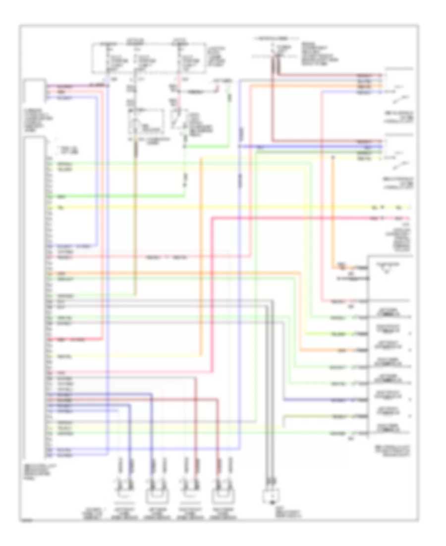
Anti-lock Brake Wiring Diagrams for Dodge Stealth R/T 1996
List of elements for Anti-lock Brake Wiring Diagrams for Dodge Stealth R/T 1996:
- (not used)
- (on each wheel hub assembly)
- (w/ awd)
- A64
- A65
- Abs control unit (behind right rear quarter
- Abs hydraulic unit (on right front of engine compt)
- Abs indicator
- Abs motor relay (on abs hydraulic unit)
- Abs valve relay (on abs hydraulic unit)
- C69
- C71
- C79
- C83
- Combination meter
- D04
- Data link connector 1 (partial) (right of steering column)
- Engine compartment relay box (on right side of engine compt, near shock tower)
- Fusible link 7 60a
- G sensor (w/ awd only) (under center console, near shift lever)
- G307 (below right rear window)
- Hot at all times
- Hot in on
- Hot in on or start
- Junction block (under left side of dash)
- Left front exhaust valve
- Left front intake valve
- Left front wheel speed sensor
- Left rear exhaust valve
- Left rear intake valve
- Left rear wheel speed sensor
- Multi- purpose fuse 11 15a
- Multi- purpose fuse 17 15a
- Multi- purpose fuse 3 10a
- Nca
- Panel)
- Pins 1-29 not used
- Pnk
- Pump motor
- Red
- Right front exhaust valve
- Right front intake valve
- Right front wheel speed sensor
- Right rear exhaust valve
- Right rear intake valve
- Right rear wheel speed sensor
- Stop- light switch (on bracket, above brake pedal)
 English