ANTI-LOCK BRAKES
Anti-lock Brakes Wiring Diagram for Dodge Stratus R/T 2005
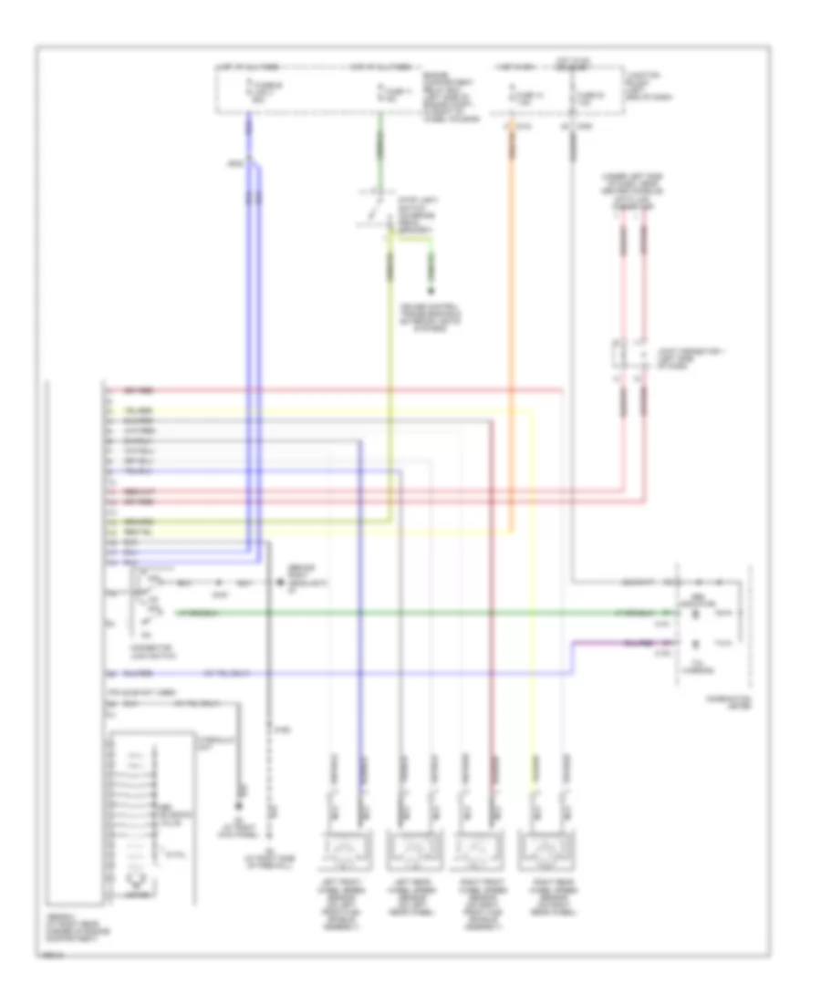
List of elements for Anti-lock Brakes Wiring Diagram for Dodge Stratus R/T 2005:
- (behind right headlight) g1
- (pin 22-29 not used)
- (under left side of dash, near center console) data link connector
- (w/ tcl only)
- Abs ecu (at right rear corner of engine compartment)
- Abs indicator
- Abs solenoid valve
- C101
- C102
- C308
- C312
- Combination meter
- Connector lock switch
- Cruise control, transmissions & exterior lights systems
- Engine compartment relay box (left side of engine compt, in front of wheel housing)
- Fuse 11 15a
- Fuse 13 7.5a
- Fuse 23 7.5a
- Fusible link 3 60a
- G2 (at right side of firewall)
- G3 (at right kick panel)
- Hot at all times
- Hot in on
- Hot in on or start
- Hydraulic unit
- Joint connector 1 (left side of dash)
- Junction block (left end of dash)
- Left front wheel speed sensor (on left front hub/ spindle assembly)
- Left rear wheel speed sensor (on left rear wheel)
- Motor
- Nca
- Off
- Right front wheel speed sensor (on right front hub/ spindle assembly)
- Right rear wheel speed sensor (on right rear wheel)
- S002
- S167
- S168
- Stop light switch (on brake pedal bracket)
- Tcl warning
- W/tcl
 English