AUTOMOTIVE ELECTRICIANS PORTAL

ANTI-LOCK BRAKES – Ford Club Wagon E150 1995 – SYSTEM WIRING DIAGRAMS

ANTI-LOCK BRAKES

Anti-lock Brake Wiring Diagrams, 4 Wheel ABS for Ford Club Wagon E150 1995

Anti-lock Brake Wiring Diagrams, 4 Wheel ABS for Ford Club Wagon E150 1995 https://portal-diagnostov.com/license.html
https://portal-diagnostov.com/license.html Automotive Electricians Portal FZCO Automotive Electricians Portal FZCO
Download PDF file

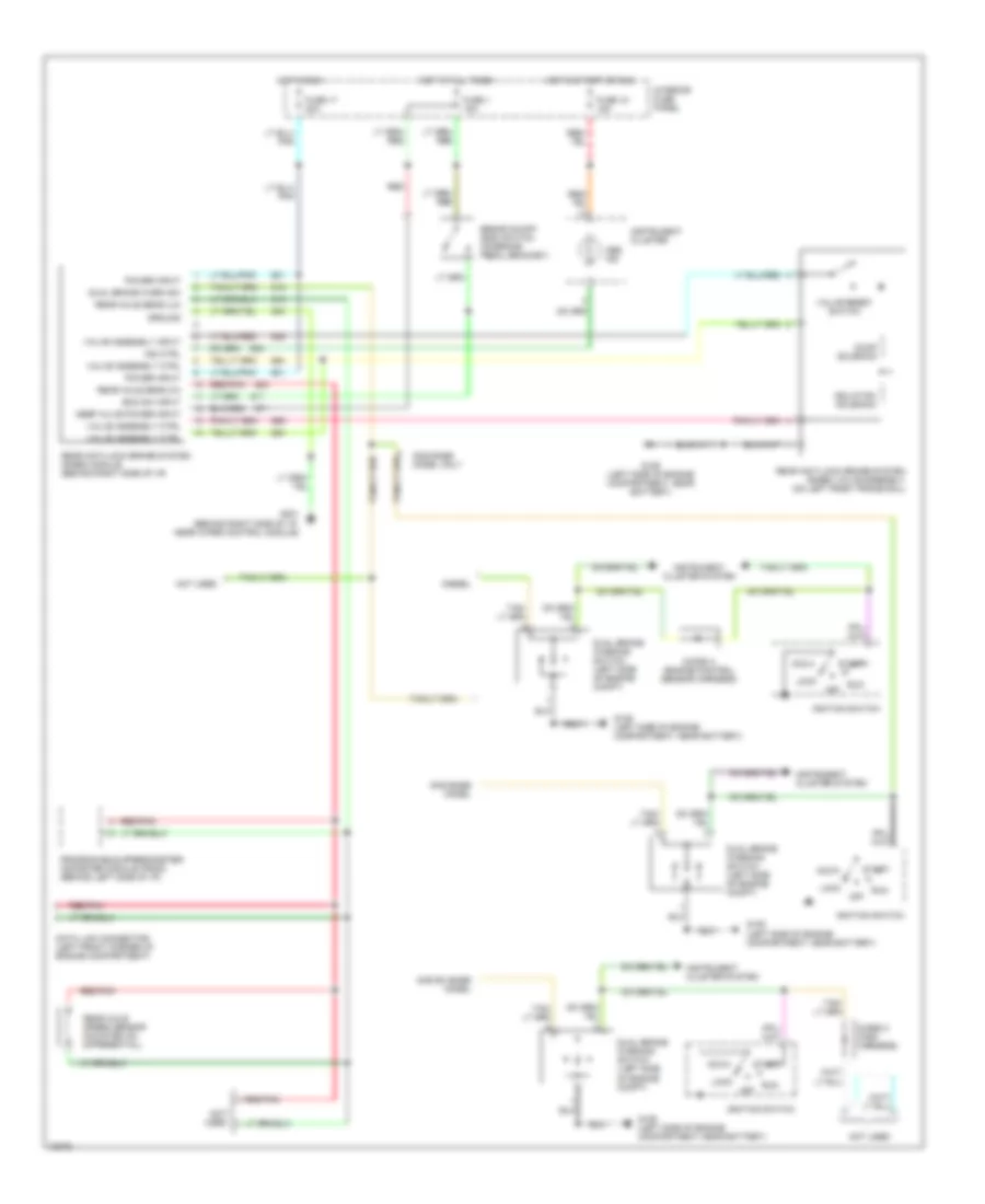
List of elements for Anti-lock Brake Wiring Diagrams, 4 Wheel ABS for Ford Club Wagon E150 1995:

  • (diesel)
  • (gas)
  • (left side of engine compartment)
  • 4 wheel anti-lock brakes (4wabs) hydraulic unit (on left front frame rail)
  • 4 wheel anti-lock brakes (4wabs) module (on left front frame rail)
  • 4wabs pump motor (on left front frame rail)
  • 4wabs relay
  • Abs data link connector (below left side of i/p)
  • Abs data link connector (below left side of i/p) (diesel) (left side of engine compartment) (gas)
  • Abs ind
  • Abs ind ctrl
  • Acc
  • Brake fluid level sw
  • Brake on/off (boo) switch (on brake pedal bracket)
  • Brake sw input
  • Brake warning ind
  • Diesel
  • Diode a (engine control sensor harness)
  • Diode c (main harness)
  • Dual brake warning switch (left side of engine compt)
  • Emf ctrl output
  • Engine compartment fuse panel
  • Fuse 1 15a
  • Fuse 17 20a
  • Fuse 18 15a
  • Fuse u 30a
  • Fuse v 60a
  • G106 (left side of engine compartment, near battery)
  • G106 (left side of engine compt, near battery)
  • G206 (attached to instrument panel assembly, behind cluster)
  • Gas
  • Hot at all times
  • Hot in run
  • Hot in run or start
  • Ignition switch
  • Ind ctrl
  • Instrument cluster
  • Instrument cluster system
  • Interior fuse panel
  • L fnt dump sol
  • L fnt iso sol
  • L fnt sig ground
  • L fnt speed input
  • Left front dump valve
  • Left front iso valve
  • Left front wheel sensor
  • Lock
  • Module ground
  • Module power
  • Motor power
  • Not used
  • Off
  • Park brake switch (above left cowl panel)
  • Pnk
  • Power ground 1
  • Power ground 2
  • Programmable speedometer/ odometer module (psom) (behind left side of i/p)
  • Pump motor power
  • Rear axle speed sensor (mounted on differential)
  • Rear dump sol
  • Rear dump valve
  • Rear iso sol
  • Rear iso valve
  • Rear reset
  • Rear reset switch
  • Rear sig ground
  • Rear speed input
  • Red/pnk
  • Right front dump valve
  • Right front iso valve
  • Right front wheel sensor
  • Rly ctrl output
  • Rt fnt dump sol
  • Rt fnt iso sol
  • Rt fnt sig ground
  • Rt fnt speed input
  • Run
  • Serial communication
  • Start
  • Tan
  • Tan/red
  • W/ premium sound system

Anti-lock Brake Wiring Diagrams, Rear Wheel ABS for Ford Club Wagon E150 1995

Anti-lock Brake Wiring Diagrams, Rear Wheel ABS for Ford Club Wagon E150 1995 https://portal-diagnostov.com/license.html
https://portal-diagnostov.com/license.html Automotive Electricians Portal FZCO Automotive Electricians Portal FZCO
Get access to all wiring diagrams of the carDownload PDF file

List of elements for Anti-lock Brake Wiring Diagrams, Rear Wheel ABS for Ford Club Wagon E150 1995:

  • Abs ind
  • Acc
  • Boo sw input
  • Brake on/off (boo) switch (on brake pedal bracket)
  • Data link connector (left front corner of engine compartment)
  • Diesel
  • Diode a (engine control sensor harness)
  • Diode c (main harness)
  • Dual brake warn sw
  • Dual brake warning switch (left side of engine compt)
  • Dump solenoid
  • Fuse 1 15a
  • Fuse 17 20a
  • Fuse 18 15a
  • G106 (left side of engine compartment, near battery)
  • G201 (behind right side of i/p, near wiper control module)
  • Gas base model
  • Gas base model only
  • Gas ex base model
  • Ground
  • Hot at all times
  • Hot in run
  • Hot in start or run
  • Ignition switch
  • Ind ctrl
  • Instrument cluster
  • Instrument cluster system
  • Interior fuse panel
  • Isolation solenoid
  • Keep alive power input
  • Lock
  • Not used
  • Off
  • Power input
  • Programable speedometer/ odometer module (psom) (behind left side of i/p)
  • Rear anti-lock brake system (rabs) module (behind right side of i/p)
  • Rear anti-lock brake system (rabs) valve assembly (on left front frame rail)
  • Rear axle sens (hi)
  • Rear axle sens (lo)
  • Rear axle speed sensor (mounted on differential)
  • Red
  • Red/pnk
  • Run
  • Start
  • Valve assembly ctrl
  • Valve assembly input
  • Valve reset switch