ANTI-LOCK BRAKES
Anti-lock Brake Wiring Diagrams, with Traction Control for Ford Contour SVT 1999

List of elements for Anti-lock Brake Wiring Diagrams, with Traction Control for Ford Contour SVT 1999:
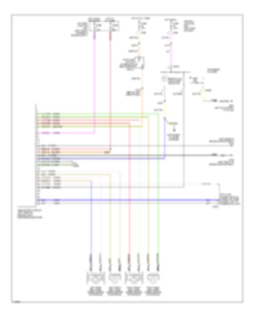
Anti-lock Brake Wiring Diagrams, without Traction Control for Ford Contour SVT 1999
List of elements for Anti-lock Brake Wiring Diagrams, without Traction Control for Ford Contour SVT 1999: