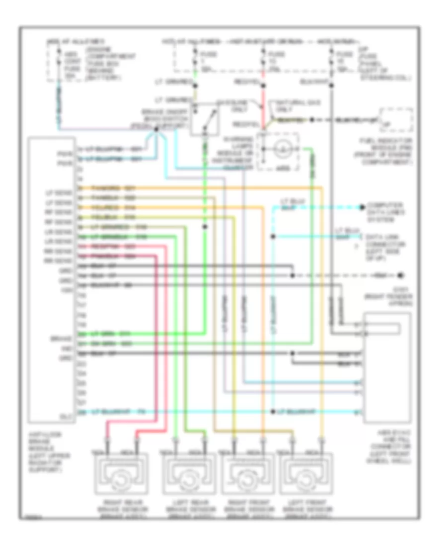
ANTI-LOCK BRAKES
Anti-lock Brake Wiring Diagrams for Ford Crown Victoria 1996
List of elements for Anti-lock Brake Wiring Diagrams for Ford Crown Victoria 1996:
- (right fender apron)
- Abs
- Abs cont fuse 30a
- Abs evac and fill connector (left front wheel well)
- Anti-lock brake module (left upper radiator support)
- Brake
- Brake on/off (boo) switch (pedal support)
- Computer data lines system
- Data link connector (left side of i/p)
- Dlc
- Engine compartment fuse box (behind battery)
- Fuel indicator module (fim) (front of engine compartment)
- Fuse 10a
- Fuse 15a
- G101
- Gasoline only
- Grd
- Hot at all times
- Hot in run
- Hot in start or run
- I/p
- I/p fuse panel (left of steering col.)
- Ign
- Ind
- Left front brake sensor (brake ass'y)
- Left rear brake sensor (brake ass'y)
- Lf sens
- Lr sens
- Natural gas only
- Nca
- Pwr
- Red/pnk
- Rf sens
- Right front brake sensor (brake ass'y)
- Right rear brake sensor (brake ass'y)
- Rr sens
- Warning lamps module or instrument cluster
 English