ANTI-LOCK BRAKES
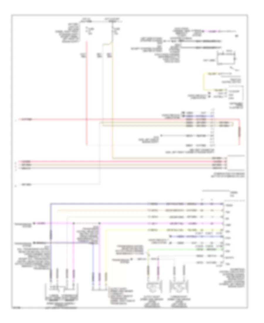
Anti-lock Brakes Wiring Diagram, with Stability Assist (1 of 2) for Ford Cutaway E250 2010

List of elements for Anti-lock Brakes Wiring Diagram, with Stability Assist (1 of 2) for Ford Cutaway E250 2010:
- Anti-lock brake system (abs) module (diesel: left side of engine compt) (except diesel: left front of engine compt)
- Battery junction box (bjb) (diesel: right front of engine compt) (except diesel: left front of engine compt)
- Can +
- Can -
- Can2 +
- Can2 -
- Cbb53
- Computer data lines system
- Fuse 40a
- G102 (stripped chassis: left rear of engine compt) (except stripped chassis: left side of engine compt)
- Gd121
- Ground
- Hot at all times
- Left front wheel speed sensor (left front wheel hub assembly)
- Left rear wheel speed sensor (left rear wheel hub assembly)
- Lf_sen+
- Lf_sen-
- Lr_sen+
- Lr_sen-
- Nca
- Rca09
- Rca17
- Rca18
- Rca19
- Rca20
- Red
- Rf_sen+
- Rf_sen-
- Right front wheel speed sensor (right front wheel hub assembly)
- Right rear wheel speed sensor (right rear wheel hub assembly)
- Rr_sen+
- Rr_sen-
- Sbb33
- Sbb47
- Steer angle 1
- Steer angle 2
- Steer sens gnd
- Vbatt
- Vca03
- Vca04
- Vca05
- Vca06
- Vcs06
- Vcs07
- Vdb04
- Vdb05
- Vpwr
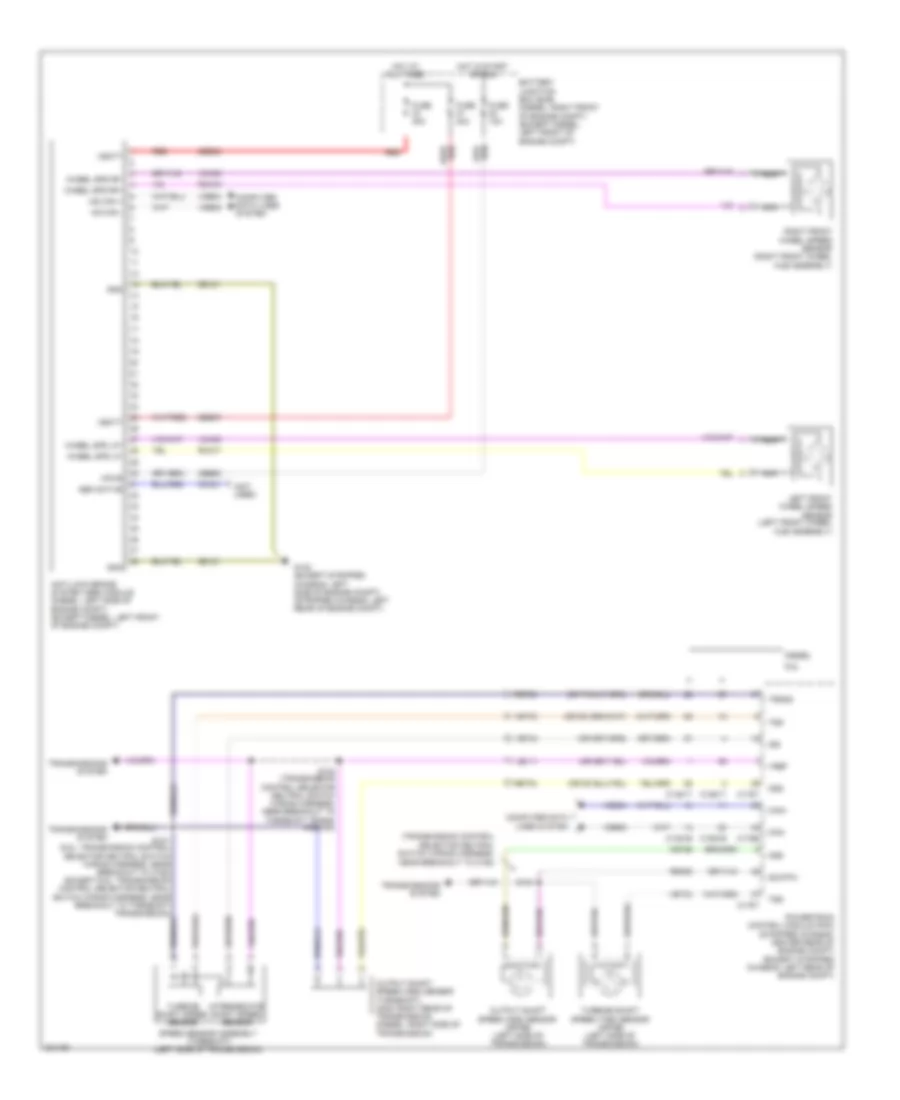
Anti-lock Brakes Wiring Diagram, with Stability Assist (2 of 2) for Ford Cutaway E250 2010
List of elements for Anti-lock Brakes Wiring Diagram, with Stability Assist (2 of 2) for Ford Cutaway E250 2010:
- (left side of dash) (stripped chassis) g205
- (main wiring harness, near breakout to audio control module (acm))
- (main wiring harness, near breakout to g207) (stripped chassis) s250
- (not used)
- (transmission control selector neutral switch wiring harness,
- 6.8l
- Abs test connector (gas: left front corner of engine compt)
- Battery junction box (bjb) (diesel: right front of engine compt) (except diesel: left front of engine compt)
- C1381b
- C1381t
- C1551b
- C1551t
- C175b
- C175t
- Can+
- Can-
- Cbb53
- Computer data lines system
- Diesel
- Fuse 10a
- Fuse 40a
- G103 (gas: left side of engine compt)
- G201 (except stripped chassis) (center of dash)
- Gd121
- Hot at all times
- Hot in start or run
- Instrument panel cluster (ic)
- Interior lights system
- Intermediate shaft speed sensor
- Iss
- Le111
- Near breakout to c192)
- Oss
- Output shaft speed (oss) sensor (4r75e) (left side of transmission)
- Output shaft speed (oss) sensor (torqshift) (gas: right rear of transmission) (diesel: right side of transmission)
- Powertrain control module (pcm) (stripped chassis: center rear of engine compt) (except stripped chassis: left rear of engine compt)
- Re406
- Ret04
- Ret24
- S101 (6.8l: transmission control selector neutral switch wiring harness, near breakout to c192) (except 6.8l: transmission control selector neutral switch wiring harness, near breakout to torqshift transmission)
- S102 (transmission control selector neutral switch wiring harness, near breakout to torqshift trans- mission)
- S104
- S264 (except stripped chassis)
- Sbb47
- Sig rtn
- Speed sensor assembly (torqshift) (left side of transmission)
- Steering position sensor (bottom of steering column)
- Tc on/off
- Traction control switch
- Transmissions system
- Trgnd
- Tss
- Turbine shaft speed (tss) sensor (4r75e) (left side of transmission)
- Turbine shaft speed sensor
- Vdb04
- Vdb05
- Ve744
- Vet26
- Vet33
- Vref
Anti-lock Brakes Wiring Diagram, without Stability Assist for Ford Cutaway E250 2010
List of elements for Anti-lock Brakes Wiring Diagram, without Stability Assist for Ford Cutaway E250 2010:
- (not used)
- (transmission control selector neutral switch wiring harness,
- 6.8l
- Abs active
- Anti-lock brake system (abs) module (diesel: left side of engine compt) (except diesel: left front of engine compt)
- Battery junction box (bjb) (diesel: right front of engine compt) (except diesel: left front of engine compt)
- C1381b
- C1381t
- C1551b
- C1551t
- C175b
- C175t
- Can+
- Can-
- Cbb53
- Cca01
- Computer data lines system
- Diesel
- Fuse 10a
- Fuse 40a
- G102 (except stripped chassis: left side of engine compt) (stripped chassis: left rear of engine compt)
- Gd121
- Gnd
- Hot at all times
- Hot in start or run
- Hs can +
- Hs can -
- Intermediate shaft speed sensor
- Iss
- Le111
- Left front wheel speed sensor (left front wheel hub assembly)
- Nca
- Near breakout to c192)
- Oss
- Output shaft speed (oss) sensor (4r75e) (left side of transmission)
- Output shaft speed (oss) sensor (torqshift) (gas: right rear of transmission) (diesel: right side of transmission)
- Powertrain control module (pcm) (stripped chassis: center rear of engine compt) (except stripped chassis: left rear of engine compt)
- Rca17
- Rca19
- Re406
- Red
- Ret04
- Ret24
- Right front wheel speed sensor (right front wheel hub assembly)
- S101 (6.8l: transmission control selector neutral switch wiring harness, near breakout to c192) (except 6.8l: transmission control selector neutral switch wiring harness, near breakout to torqshift transmission)
- S102 (transmission control selector neutral switch wiring harness, near breakout to torqshift trans- mission)
- S104
- Sbb33
- Sbb47
- Sig rtn
- Speed sensor assembly (torqshift) (left side of transmission)
- Transmissions system
- Trgnd
- Tss
- Turbine shaft speed (tss) sensor (4r75e) (left side of transmission)
- Turbine shaft speed sensor
- Vbatt
- Vca03
- Vca05
- Vdb04
- Vdb05
- Ve744
- Vet26
- Vet33
- Vpwr
- Vref
- Wheel spd lf+
- Wheel spd lf-
- Wheel spd rf+
- Wheel spd rf-