ANTI-LOCK BRAKES
Anti Lock Brake Wiring Diagram, 4 Wheel ABS for Ford Econoline E250 1994

List of elements for Anti Lock Brake Wiring Diagram, 4 Wheel ABS for Ford Econoline E250 1994:
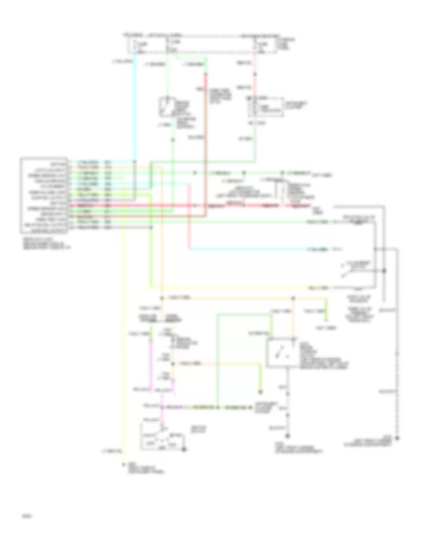
Anti Lock Brake Wiring Diagram, Rear Wheel ABS for Ford Econoline E250 1994
List of elements for Anti Lock Brake Wiring Diagram, Rear Wheel ABS for Ford Econoline E250 1994: