ANTI-LOCK BRAKES
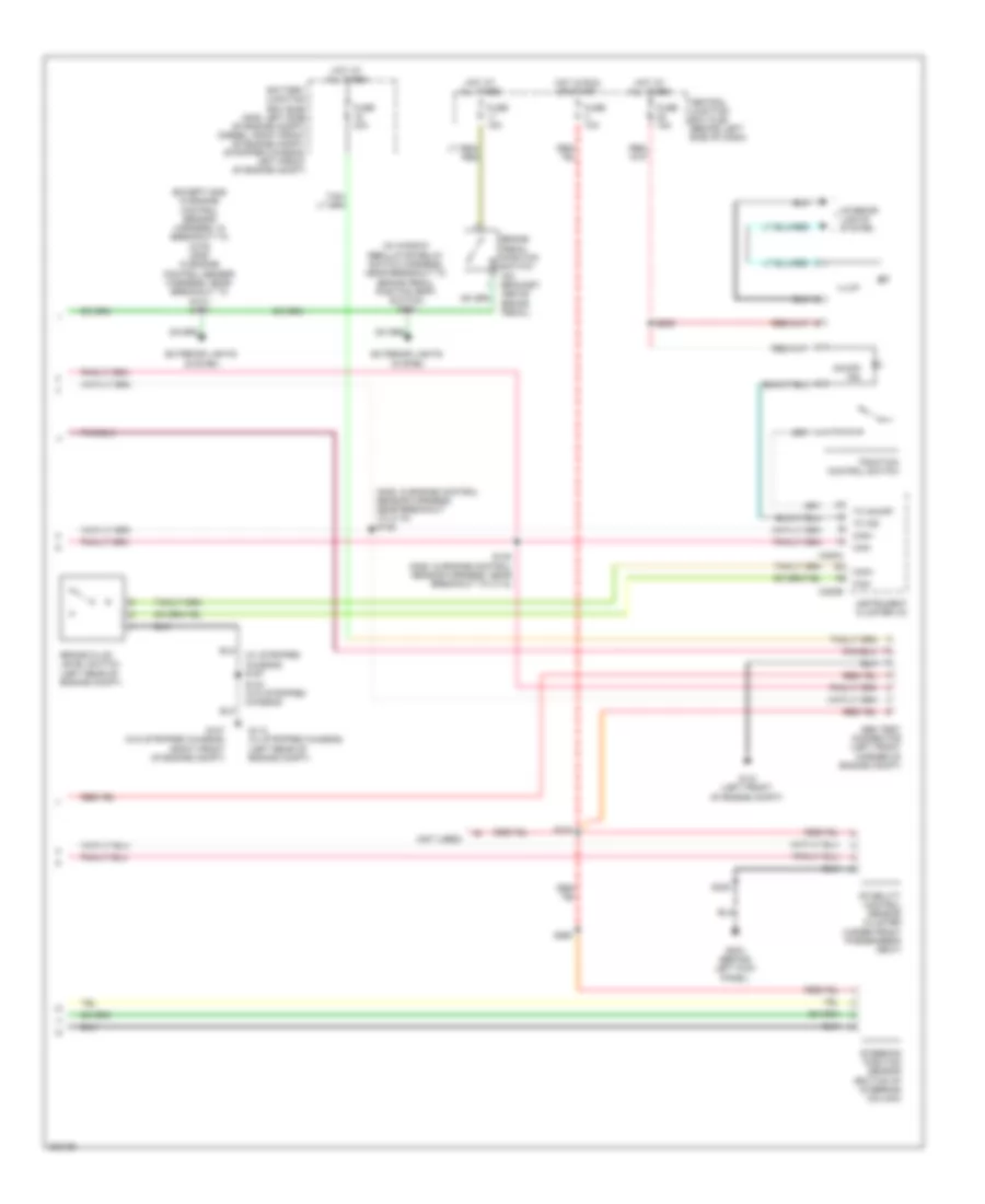
Anti-lock Brakes Wiring Diagram, with Stability Assist (1 of 2) for Ford Econoline E250 2008

List of elements for Anti-lock Brakes Wiring Diagram, with Stability Assist (1 of 2) for Ford Econoline E250 2008:
- (diesel: left side of engine compt) (gas: left front of engine compt) (stripped chassis: left front corner of engine compt) g105
- (except stripped chassis: below left side of dash) (stripped chassis: behind left side of dash) data link connector (dlc)
- (except stripped chassis: in main harness, near breakout to brake pedal position (bpp) switch) (stripped chassis: in main harness, near breakout to inertia fuel shutoff (ifs) switch) s269
- (in main harness, near breakout to inertia fuel shutoff (ifs) switch s228
- Abs control module (left front of engine compt)
- Angle a/1
- Angle b/2
- Battery junction box (bjb) (gas: left side of engine compt) (diesel: right front of engine compt) (stripped chassis: left front of engine compt)
- Bpp
- Brake pressure switch (left rear of eng compt)
- Brk press sw
- C175b
- C175e
- C175t
- Can +
- Can -
- Can 2 high
- Can 2 low
- Can+
- Can-
- Fuse 40a
- G122 (left rear of engine compt)
- Ground
- Hot at all times
- Left front wheel speed sensor (at left front wheel hub assembly)
- Left rear wheel speed sensor (at left rear wheel hub assembly)
- Lf_gnd
- Lf_sen
- Lr_gnd
- Lr_sen
- Nca
- Powertrain control module (pcm) (stripped chassis: right rear of engine compt) (diesel & gas: left rear of engine compt)
- Red/ pnk
- Red/pnk
- Ref
- Rf_gnd
- Rf_sen
- Right front wheel speed sensor (at right front wheel hub assembly)
- Right rear wheel speed sensor (at right rear wheel hub assembly)
- Rr_gnd
- Rr_sen
- S139 (in engine control sensor & fuel charge harness, near breakout for c192)
- Transmissions system
- Vbatt
- Vpwr
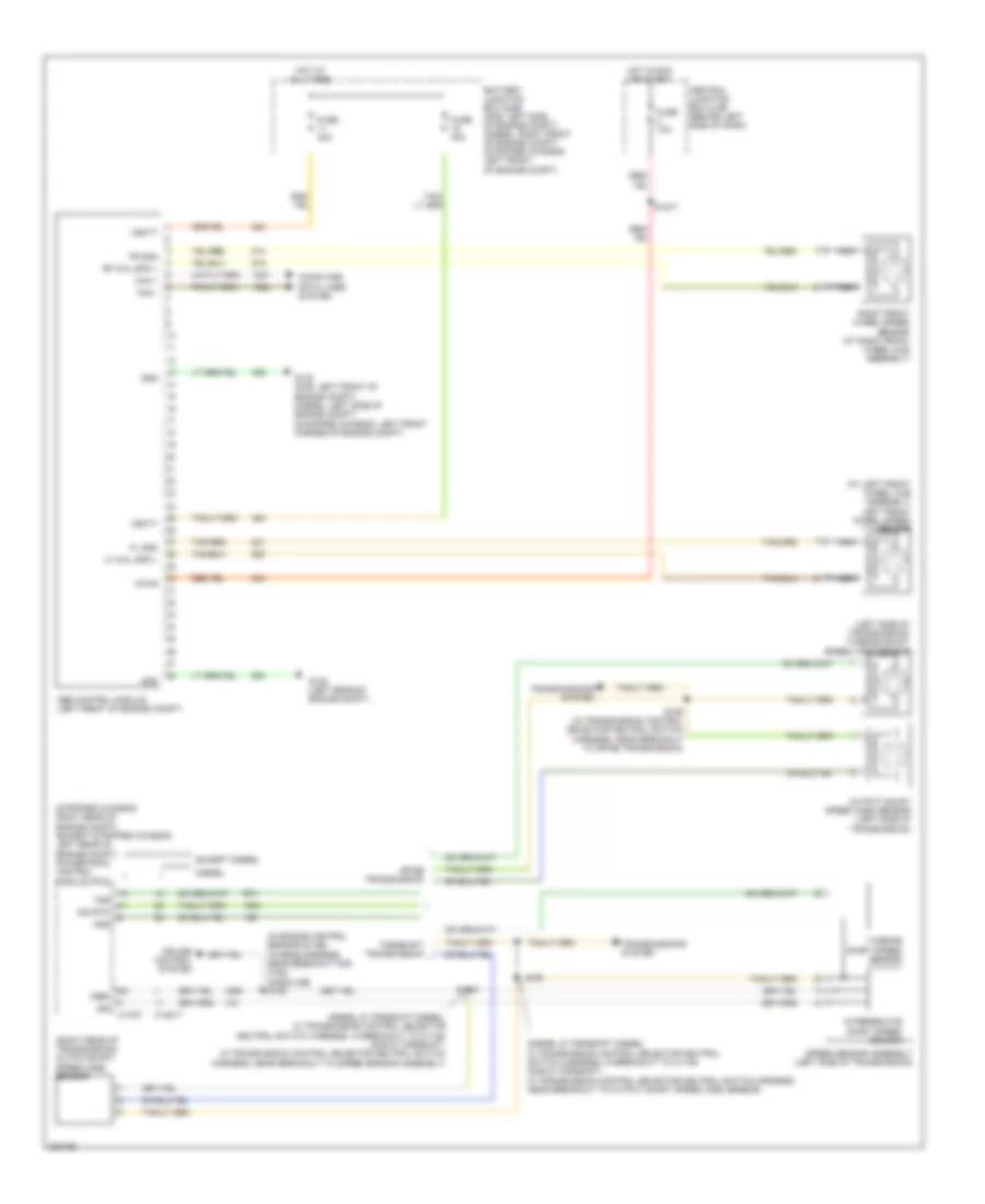
Anti-lock Brakes Wiring Diagram, with Stability Assist (2 of 2) for Ford Econoline E250 2008
List of elements for Anti-lock Brakes Wiring Diagram, with Stability Assist (2 of 2) for Ford Econoline E250 2008:
- (except gas: in engine control sensor harness, in breakout to c219) (gas: in engine control sensor harness, near breakout to g101) s174
- (gas: in engine control sensor harness, near breakout to c110) s146
- (in window regulator relay switch harness, near breakout to brake pedal position (bpp) switch) s224
- (not used)
- (w/ stripped chassis) s197
- Abs test connector (left front corner of engine compt)
- Battery junction box (bjb) (gas: left side of engine compt) (diesel: right front of engine compt) (stripped chassis: left front of engine compt)
- Brake fluid level switch (left rear of engine compt)
- Brake pedal position switch (on bracket, above brake pedal)
- C220a
- C220b
- Can+
- Can-
- Central junction box (cjb) (behind left side of dash)
- Exterior lights system
- Fuse 10a
- Fuse 15a
- Fuse 40a
- G107 (w/o stripped chassis) (right front of engine compt)
- G113 (w/ stripped chassis) (left rear of engine compt)
- G121 (left front of engine compt)
- G204 (behind left kick panel)
- Hot at all times
- Hot in run or start
- Illum
- Instrument cluster (ic)
- Interior lights system
- On/off ind
- S143 (w/o stripped chassis)
- S148 (gas: in engine control sensor harness, near breakout to c110)
- S205
- S216
- S235
- S260
- Stability control sensor cluster (under front passenger's seat)
- Steering position sensor (bottom of steering column)
- Tc ind
- Tc on/off
- Traction control switch
Anti-lock Brakes Wiring Diagram, without Stability Assist for Ford Econoline E250 2008
List of elements for Anti-lock Brakes Wiring Diagram, without Stability Assist for Ford Econoline E250 2008:
- (at left front wheel hub assembly) left front wheel speed sensor
- (diesel & torqshift diesel: in transmission control selector neutral switch harness, in breakout to c1148) (gas & torqshift: in transmission control selector neutral switch harness, near breakout to output shaft speed (oss) sensor)
- (diesel & torqshift diesel: in transmission control selector neutral switch harness, in breakout to c1148) (gas & torqshift: in transmission control selector neutral switch harness, near breakout to speed sensor assembly)
- (in engine control sensor & fuel charge harness, near breakout for c192) (gasoline) s139
- (left side of transmission) turbine shaft speed (tss) sensor
- (right rear of transmission) outputshaft speed (oss) sensor
- (stripped chassis: right rear of engine compt) (except stripped chassis: left rear of engine compt) powertrain control module (pcm)
- 4r75e transmission
- Abs control module (left front of engine compt)
- Battery junction box (bjb) (gas: left side of engine compt) (diesel: right front of engine compt) (stripped chassis: left front of engine compt)
- C1381t
- C175t
- Can +
- Can -
- Central junction box (cjb) (behind left side of dash)
- Computer data lines system
- Cruise control system
- Diesel
- Except diesel
- Fl gnd
- Fr gnd
- Fuse 10a
- Fuse 40a
- G105 (gas: left front of engine compt) (diesel: left side of engine compt) (stripped chassis: left front corner of engine compt)
- G122 (left rear of engine compt)
- Gnd
- Hot at all times
- Hot in run or start
- Intermediate shaft speed sensor
- Iss
- Lf whl spd +
- Nca
- Oss
- Output shaft speed (oss) sensor (left side of transmission)
- Rf whl spd +
- Right front wheel speed sensor (at right front wheel hub assembly)
- S1037
- S1077
- S198
- S198 (in transmission control selector neutral switch harness, near breakout to 4r75e transmission)
- Sig rtn
- Speed sensor assembly (left side of transmission)
- Torqshift transmission
- Transmissions system
- Tss
- Turbine shaft speed sensor
- Vbatt
- Vpwr
- Vref