ANTI-LOCK BRAKES
Anti-lock Brakes Wiring Diagram for Ford Escape 2004
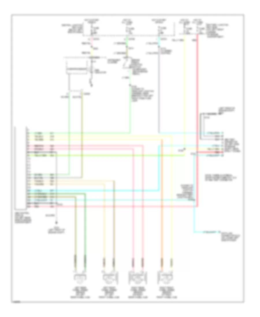
List of elements for Anti-lock Brakes Wiring Diagram for Ford Escape 2004:
- (in dash to headlamp junction harness, near battery junction box) s125
- (left front of engine compt) g104
- Abs control module (on left rear side of engine compartment)
- Abs indicator
- Abs test connector (on left side of engine compt, near
- Battery junction box (bjb) (on left front corner of engine compartment)
- Brake pedal position switch (on bracket, above brake pedal)
- C220b
- C220c
- C270a
- C270c
- C270e
- Central junction box (cjb) (below left end of dash)
- Data link connector (dlc) (on lower left side of dash)
- Fuse 10a
- Fuse 15a
- Fuse 25a
- Fuse 5a
- Fuse 60a
- G104 (left front of engine compt)
- Hot at all times
- Hot in start or run
- Instrument cluster
- Left front wheel speed sensor (at left front wheel hub)
- Left rear wheel speed sensor (on left rear wheel hub)
- Microprocessor
- Note: there is internal shorting between pin 1 & 5 of abs test connector
- Red
- Red/pnk
- Right front wheel speed sensor (at right front wheel hub)
- Right rear wheel speed sensor (on right rear wheel hub)
- S119 (w/ speed control)
- S123
- S124
- S126
- S132
- S139 (in dash to headlamp junction harness, near breakout for left front park/turn lamp)
- S222
- S314
- Strut tower)
 English