ANTI-LOCK BRAKES
Anti-lock Brakes Wiring Diagram, Early Production for Ford Excursion 2001

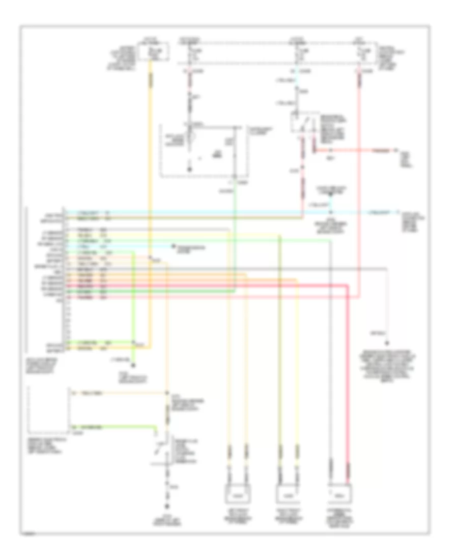
List of elements for Anti-lock Brakes Wiring Diagram, Early Production for Ford Excursion 2001:
- 22k ohm
- 4-wheel anti-lock brake system (4wabs) module (in left front of engine compartment)
- 4wabs ind ctrl
- 4x4 high/low ind
- 5.6k ohm
- Anti-lock brake indicator
- Battery junction box (in left side of engine compt, on top of wheelwell)
- Bpp switch feed
- Brake fluid level sw
- Brake fluid level switch (on brake fluid reservoir)
- Brake pedal position (bpp) switch (behind left side of dash, above brake pedal)
- C104a
- C104b
- C240a
- C242b
- C250a
- C250c
- Central junction box (behind lower left side of dash)
- Computer data lines system
- Data link connector (behind center of dash)
- Diagnostic circuit
- Differential speed sensor (dss) (on center of rear axle)
- Engine controls system (generic electronic module (gem), instrument cluster, central junction box, overhead console module, powertrain control module, speed control servo)
- Fuse 10a
- Fuse 5a
- Fuse 60a
- G100 (left front of engine compt)
- G104 (rear of left front fender)
- G200 (left kick panel)
- Generic electronic module (gem) (behind lower left side of dash)
- Ground
- Hot at all times
- Hot in run
- Hot in run or start
- Ignition feed
- Instrument cluster
- Left front anti-lock brake sensor (at wheel)
- Left front sensor (high)
- Left front sensor (low)
- Nca
- Power (b+)
- Rear sensor (high)
- Rear sensor (low)
- Red/pnk
- Right front anti-lock brake sensor (at wheel)
- Right front sensor (high)
- Right front sensor (low)
- S102
- S108
- S165 (engine harness, left side of engine compt)
- S178 (engine harness, left side of engine compt)
- S201
- S271
- S288
- Tan/red
- Transmissions system
- Vss (+)
Anti-lock Brakes Wiring Diagram, Late Production for Ford Excursion 2001
List of elements for Anti-lock Brakes Wiring Diagram, Late Production for Ford Excursion 2001:
- 22k ohm
- 4wabs ind
- 4wd in
- 5.6k ohm
- Anti-lock brake indicator
- Anti-lock brake system module (left front of engine compt)
- Battery
- Battery junction box (in left side of engine compt, on top of wheelwell)
- Bpp switch
- Brake fluid level switch (on brake fluid reservoir)
- Brake fluid lv
- Brake pedal position (bpp) switch (behind left side of dash, above brake pedal)
- C240a
- C242b
- C250a
- C250c
- Central junction box (behind lower left side of dash)
- Computer data lines system
- Data link connector (behind center of dash)
- Diag trig
- Differential speed sensor (dss) (on center of rear axle)
- Engine controls system (generic electronic module (gem), instrument cluster, central junction box, overhead console module, powertrain control module, speed control servo)
- Fuse 10a
- Fuse 5a
- Fuse 60a
- G100 (left front of engine compt)
- G104 (rear of left front fender)
- G200 (left kick panel)
- Generic electronic module (gem) (behind lower left side of dash)
- Ground
- Hot at all times
- Hot in run
- Hot in run or start
- Ign
- Instrument cluster
- Left front anti-lock brake sensor (at wheel)
- Lf sensor
- Nca
- Red/pnk
- Rf sensor
- Right front anti-lock brake sensor (at wheel)
- Rr sens low
- Rr sensor
- S102
- S108
- S137
- S157
- S165 (engine harness, left side of engine compt)
- S178 (engine harness, left side of engine compt)
- S201
- S271
- S288
- Tan/red
- Transmissions system
- Vss+