ANTI-LOCK BRAKES
Anti-lock Brake Wiring Diagrams for Ford Expedition 1999
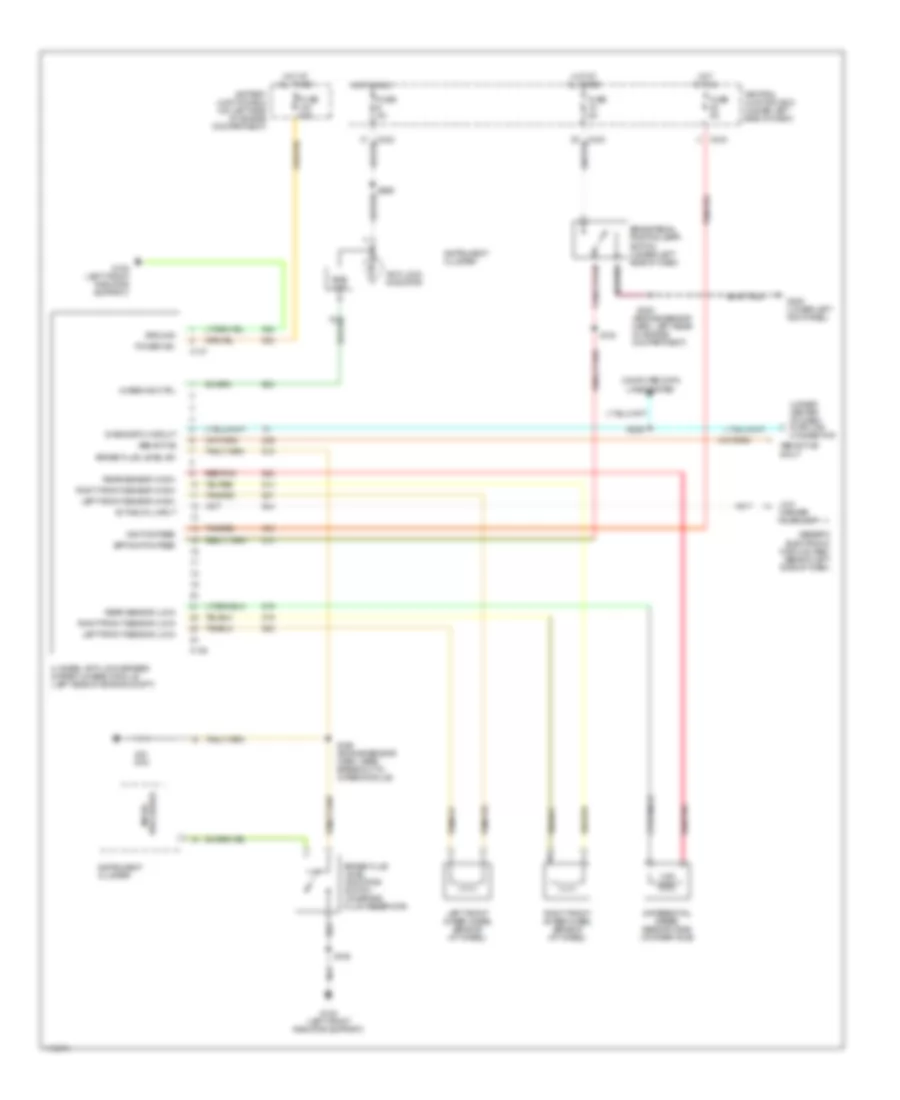
List of elements for Anti-lock Brake Wiring Diagrams for Ford Expedition 1999:
- (engine sensor harn, left rear of engine compartment)
- (under center of dash) data link connector
- 4-wheel anti-lock brakes system (4wabs) module (left side of engine compt)
- 4wabs ind ctrl
- Abs active
- Abs active input
- Active 4wl input
- Anti-lock indicator
- Battery junction box (on left side of engine compartment)
- Bias ckt
- Bpp switch feed
- Brake fluid level indicator switch (on brake fluid reservoir)
- Brake fluid level sw
- Brake pedal position (bpp) switch (under left side of dash)
- C146
- C147
- C242
- C243
- Central junction box (under left side of dash)
- Computer data lines system
- Diagnostic circuit
- Differential speed sensor (dss) (on rear axle)
- Fuse 50a
- Fuse 5a
- G108 (left front radiator support)
- G200 (lower left kick panel)
- Generic electronic module (gem) (behind left side of dash)
- Ground
- Hot at all times
- Hot in run
- Ignition feed
- Instrument cluster
- Left front 4wabs wheel sensor (at wheel)
- Left front sensor (high)
- Left front sensor (low)
- Low
- Micro- processor
- Ohm
- Power (b+)
- Rear sensor (high)
- Rear sensor (low)
- Red/pnk
- Right front 4wabs wheel sensor (at wheel)
- Right front sensor (high)
- Right front sensor (low)
- S106
- S130
- S156 (engine sensor harn, near breakout to 4wabs module)
- S208
- S229
- S265
- Tan/red
- Washer fluid lamp
 English