ANTI-LOCK BRAKES
Anti-lock Brakes Wiring Diagram for Ford Expedition 2012
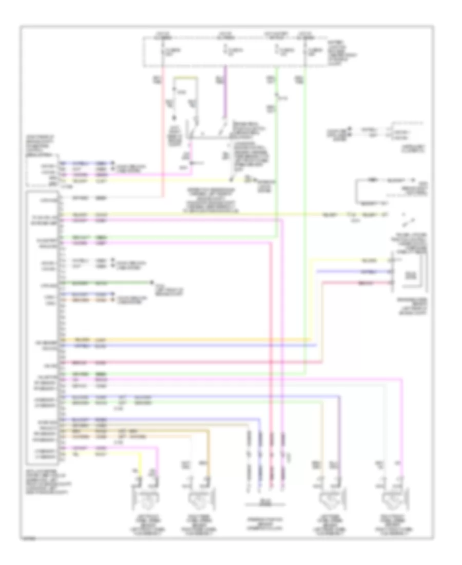
List of elements for Anti-lock Brakes Wiring Diagram for Ford Expedition 2012:
- (brake pedal support)
- (expedition: rear engine harness, left rear of engine compt) (navigator: engine compt harness, near breakout to vehicle dynamics module)
- (navigator: engine control sensor harness, near breakout to left front wheel speed sensor) s130
- (right front wheel hub assembly)
- (right rear of engine compt)
- Angle a/1
- Angle b/2
- Anti-lock brake system (abs) module (expedition: left front of engine compt) (navigator: left side of engine compt)
- Battery junction box (bjb) (center front of engine compt)
- Bpp
- Bps
- Brake booster sensor (left rear of engine compt)
- Brake pedal position switch
- C139
- C175b
- C210
- C213
- Can2 +
- Can2 -
- Cbb52
- Cca15
- Ccs01
- Ces09
- Cls17
- Computer data lines system
- Exterior lights system
- Fuse 43 5a
- Fuse 52 10a
- Fuse 68 60a
- Fuse 69 60a
- G104 (left front of engine compt)
- G107 (right rear of engine compt)
- G200 (behind right kick panel)
- Gd120
- Hot at all times
- Hot in start or run
- Hs can +
- Hs can -
- Instrument cluster (ic)
- Lca37
- Left front wheel speed sensor (left front wheel hub assembly)
- Left rear wheel speed sensor (left rear wheel hub assembly)
- Lf sensor +
- Lf sensor -
- Lr sensor +
- Lr sensor -
- Mtr gnd
- Mtr pwr
- Nca
- Power liftgate/ traction control/ hazard switch (disengage stability assist)
- Powertrain control module (pcm)
- Rca17
- Rca18
- Rca19
- Rca20
- Rca37
- Rcs02
- Rf sensor +
- Rf sensor -
- Right front wheel speed sensor
- Right rear wheel speed sensor (right rear wheel hub assembly)
- Rr sensor +
- Rr sensor -
- Run/start
- S119
- S122
- S151
- S213
- Sbb68
- Sbb69
- Solid state
- Steering position sensor (steering column)
- Swar gnd
- Swar sen sep
- Tc ivd crl sw
- Vac gnd
- Vac sensep
- Vac sig
- Valve pwr
- Vca03
- Vca04
- Vca05
- Vca06
- Vca23
- Vca24
- Vca38
- Vcs06
- Vcs07
- Vdb04
- Vdb05
 English