ANTI-LOCK BRAKES
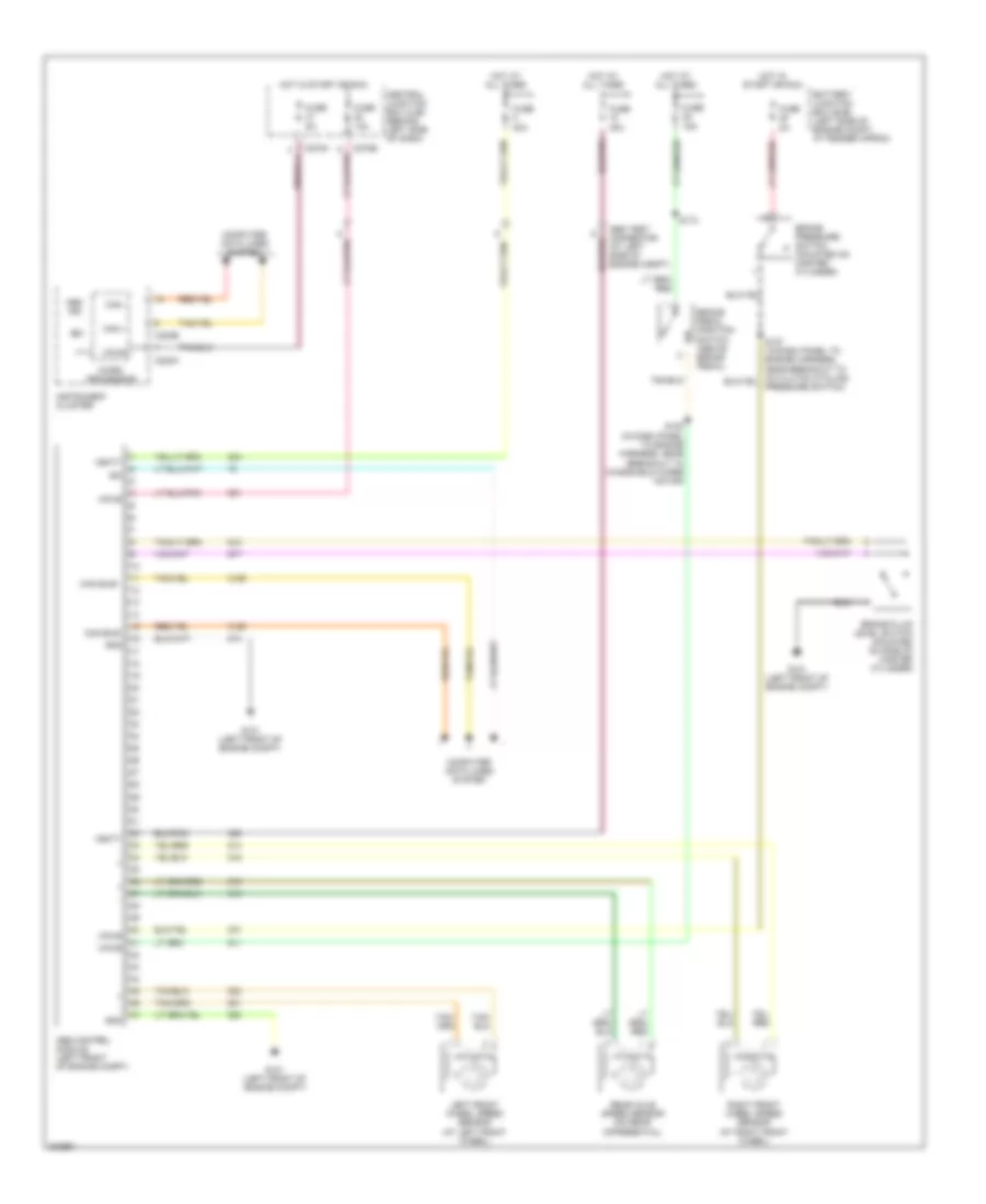
Anti-lock Brakes Wiring Diagram, with IVD for Ford Explorer 2005

List of elements for Anti-lock Brakes Wiring Diagram, with IVD for Ford Explorer 2005:
- (in dash panel to engine harness, near breakout to left horn) s120
- (left front of engine compt) g101
- 1) break pedal force switch 2) active booster solenoid
- Abs control module (left front of engine compt)
- Abs ind
- Abs test connector (at left side of engine compt)
- Battery junction box (bjb) (left side of engine compt, at fender apron)
- Brake booster sensor (on front of brake booster)
- Brake fluid level switch (mounted on side of master cylinder)
- Brake pedal position switch (above brake pedal)
- C175b
- C220a
- C220b
- C270a
- C270b
- C270h
- Can +
- Can -
- Central junction box (cjb) (behind left side of dash)
- Computer data lines system
- Fuse 10a
- Fuse 15a
- Fuse 30a
- Fuse 40a
- Fuse 5a
- Fuse 7.5a
- G101 (left front of engine compt)
- Gnd
- Hot at all times
- Hot in start or run
- Illum
- Ind
- Instrument cluster
- Interior lights system
- Iso
- Left front wheel speed sensor (at left front wheel)
- Left rear wheel speed sensor (at left rear wheel)
- Micro processor
- Powertrain control module (pcm) (at right side engine bulkhead)
- Primary brake pressure sensor (on master cylinder)
- Red
- Red/ pnk
- Red/pnk
- Redundant pedal switch (under left side dash panel)
- Right front wheel speed sensor (at right front wheel)
- Right rear wheel speed sensor (at right rear wheel)
- S171
- S173
- S200
- S201
- S264
- Secondary brake pressure sensor (on brake booster)
- Steering position sensor (at top of steering column)
- Tan
- Tcs disable
- Traction control switch
- Vbatt
- Vpwr
- Yaw velocity sensor (below center console)
Anti-lock Brakes Wiring Diagram, without IVD for Ford Explorer 2005
List of elements for Anti-lock Brakes Wiring Diagram, without IVD for Ford Explorer 2005:
- (at left side of engine compt)
- Abs control module (left front of engine compt)
- Abs ind
- Battery junction box (bjb) (left side of engine compt, at fender apron)
- Brake fluid level switch (mounted on side of master cylinder)
- Brake pedal position switch (above brake pedal)
- Brake pressure switch (mounted on master cylinder)
- C220a
- C220b
- C270b
- C270h
- Can +
- Can -
- Can bus+
- Can bus-
- Central junction box (cjb) (behind left side of dash)
- Computer data lines system
- Fuse 10a
- Fuse 15a
- Fuse 2a
- Fuse 30a
- Fuse 40a
- Fuse 5a
- G101 (left front of engine compt)
- Gnd
- Hot at all times
- Hot in start or run
- Instrument cluster
- Iso
- Left front wheel speed sensor (at left front wheel)
- Micro processor
- Pressure switch)
- Rear axle speed sensor (on rear differential)
- Right front wheel speed sensor (at right front wheel)
- S120 (in dash panel to engine harness, near breakout to windshield wiper motor)
- S173
- Vbatt
- Vpwr