ANTI-LOCK BRAKES
Anti-lock Brake Wiring Diagrams for Ford Explorer Sport Trac 2002
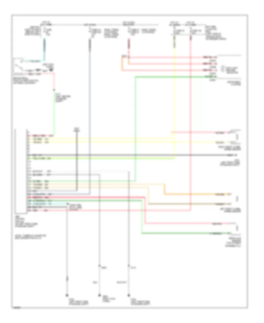
List of elements for Anti-lock Brake Wiring Diagrams for Ford Explorer Sport Trac 2002:
- (early prod) (late prod)
- (early prod) (late prod) (early prod) (late prod)
- (left kick panel) g300
- (not used)
- Abs control module (on left front side of engine compt)
- Anti-lock brakes indicator
- Battery junction box (left side of engine compt, on fender apron)
- Brake pedal position (bpp) switch (on pedal support)
- C220a
- C220b
- C220c
- Central junction box (behind left side of dash)
- Computer data lines system
- Differential)
- Fuse 128 30a
- Fuse 16 50a
- Fuse 211 fuse 22 7.5a
- Fuse 214 fuse 235 10a 5a
- Fuse 7.5a
- G101 (left front side of engine compt)
- G102 (left front side of engine compt)
- G103 (left front side of engine compt)
- G200 (right kick panel)
- Hot at all times
- Hot in run
- Hot in run or start
- Instrument cluster
- Left front wheel speed sensor
- Note: there is a shorting bar across pins 8 & 16
- Rear axle sensor (top of rear
- Red
- Red/pnk
- Right front wheel speed sensor
- S117 (left center of engine compt)
- S118
- S203
- S218
 English