ANTI-LOCK BRAKES
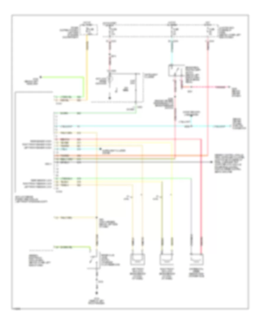
Anti-lock Brakes Wiring Diagram for Ford F450 Super Duty 1999
List of elements for Anti-lock Brakes Wiring Diagram for Ford F450 Super Duty 1999:
- (behind center of dash) data link connector
- 22k ohm
- 5.6k ohm
- Anti-lock brake indicator
- Anti-lock brake system (abs) module (left front of engine compt)
- Brake fluid level switch (on brake fluid reservoir)
- Brake pedal position (bpp) switch (behind left side of dash, above brake pedal)
- C1040
- C1041
- C243
- C250
- C253
- Computer data lines system
- Differential speed sensor (dss) (on rear axle)
- Fuse 10a
- Fuse 5a
- Fuse 60a
- G104 (rear of left front fender)
- G106 (behind left headlamp)
- G206 (behind center of dash)
- Generic control module (gem), instrument cluster, junction box fuse/relay panel, overhead trip computer (otc) module, powertrain control module, speed control servo amplifier
- Generic electronic module (gem) (behind lower left side of dash)
- Hot at all times
- Hot in run
- Hot in start or run
- Instrument cluster
- Instrument cluster system
- Junction box fuse/relay panel (behind lower left side of dash)
- Left front anti-lock brake sensor (w/ 4wal) (at wheel)
- Left front sensor (high)
- Left front sensor (low)
- Power distribution box (left side of engine compartment)
- Rear sensor (high)
- Rear sensor (low)
- Red/pnk
- Right front anti-lock brake sensor (w/ 4wal) (at wheel)
- Right front sensor (high)
- Right front sensor (low)
- S102
- S108
- S201
- S201 (main harness, behind left side of dash)
- S213
- S225
- Tan/red
- Vss (+)
- W/ 4wal
 English