ANTI-LOCK BRAKES
Anti-lock Brakes Wiring Diagram for Ford F450 Super Duty 2002
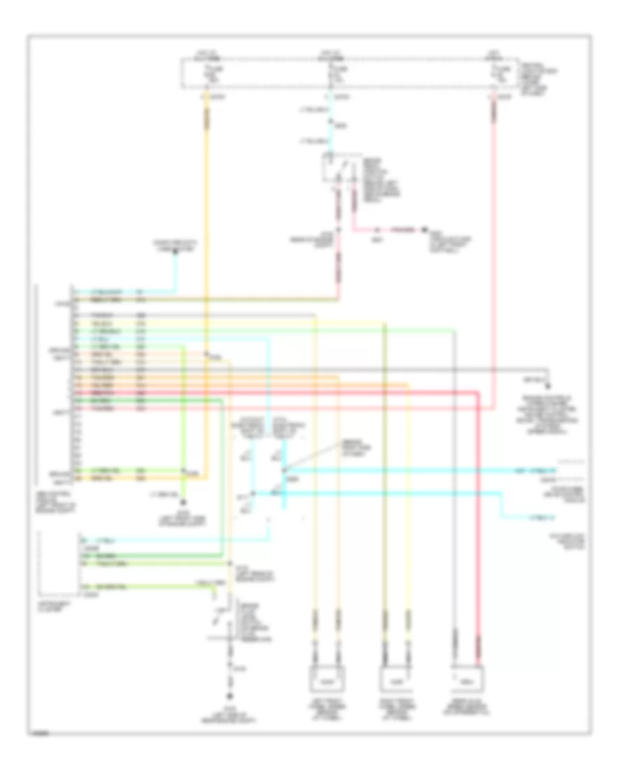
List of elements for Anti-lock Brakes Wiring Diagram for Ford F450 Super Duty 2002:
- (behind right side of dash)
- 4x4 high/low indicator switch
- Abs control module (left front of engine compt)
- Brake fluid level switch (on brake fluid reservoir)
- Brake pedal position switch (behind left side of dash, above brake pedal)
- C220b
- C220c
- C270a
- C270f
- C270m
- C281b
- Central junction box (behind lower left side of dash)
- Computer data lines system
- Engine controls, wiper/washer, instrument cluster, cruise control, sound, transmissions systems (speed signal)
- Four-wheel drive control module
- Fuse 10a
- Fuse 15a
- Fuse 60a
- G100 (left side of rear engine compt)
- G105 (left front side of engine compt)
- G300 (vehicle floor, in left front footwell)
- Ground
- Hot at all times
- Hot in run
- Instrument cluster
- Left front wheel speed sensor (at wheel)
- Nca
- Rear axle speed sensor (on differential)
- Red/pnk
- Right front wheel speed sensor (at wheel)
- S102
- S108 (rear of engine compt)
- S111
- S159
- S163
- S178 (left rear of engine compt)
- S201
- S228
- S259
- Tan/red
- Vbatt
- Vpwr
- With electronic shift on the fly
- Without electronic shift on the fly
 English