ANTI-LOCK BRAKES
Anti-lock Brakes Wiring Diagram for Ford F550 Super Duty 2008
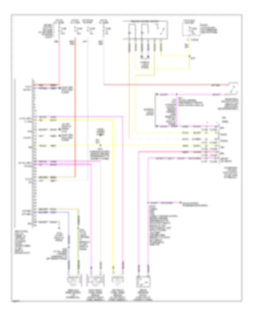
List of elements for Anti-lock Brakes Wiring Diagram for Ford F550 Super Duty 2008:
- (at left front of frame) g135
- (in engine control sensor harness, near breakout to left front of frame) s106
- (or le111)
- Abs control module (diesel: at left side of engine compt) (except diesel: at left rear of engine compt)
- Battery junction box (bjb) (at left rear of engine compt)
- Bpp
- Bps
- Brake pedal position switch (behind left side of dash, above brake pedal)
- Brake pressure switch (at bottom of master cylinder)
- C1232b
- C1232e
- C175b
- C175e
- C175t
- C2280b
- Cbb77
- Cca10
- Cca15
- Ccb08
- Cec11
- Ces09
- Computer data lines system
- Cooling fans & transmissions systems
- Diesel
- Diff sen+
- Diff sen-
- Exterior lights system
- Fl gnd
- Fr gnd
- Fuse 10a
- Fuse 40a
- Fuse 5a
- G135 (at left front of frame)
- Gas
- Gd163
- Gnd
- Hot at all times
- Hot in run or start
- Hs can +
- Hs can -
- Ign
- Interior lights system
- Kl30 p
- Kl30 v
- Left front wheel speed sensor (at left front wheel assembly)
- Lf whl spd+
- Powertrain control module (pcm) (at left side of firewall)
- Rca17
- Rca19
- Rca21
- Rear axle speed sensor (on differential)
- Red
- Rf whl spd+
- Right front wheel speed sensor (at right front wheel assembly)
- S1009 (diesel) s196 (gas) (diesel: in engine control sensor harness, near breakout to front right side of engine, on top) (gas: in backup lamp switch to rear lamp feed harness, near breakout to front left side of transmission, near top)
- S130 (in engine control sensor harness, near breakout to master cylinder)
- S211 (in main harness, near breakout behind audio control module)
- S227
- S404 (in tail lamps harness, in breakout to left rear of frame)
- S405 (in tail lamps harness, in breakout to left rear of frame)
- Sbb06
- Sbb09
- Smart junction box (on passenger side kick panel)
- Tracs
- Tracsil
- Traction control switch
- Vbpwrt (or vbpwr)
- Vca03
- Vca05
- Vca07
- Vdb04
- Vdb05
- Ve822
- Vss
- Wiper/ washer system
 English