ANTI-LOCK BRAKES
Anti-lock Brakes Wiring Diagram, with Electronic Stability Program for Ford Fiesta Titanium 2014

List of elements for Anti-lock Brakes Wiring Diagram, with Electronic Stability Program for Ford Fiesta Titanium 2014:
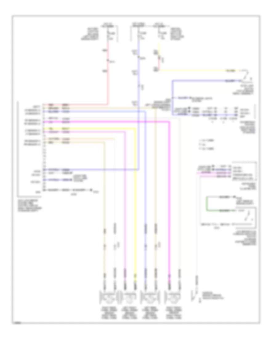
Anti-lock Brakes Wiring Diagram, without Electronic Stability Program for Ford Fiesta Titanium 2014
List of elements for Anti-lock Brakes Wiring Diagram, without Electronic Stability Program for Ford Fiesta Titanium 2014: