ANTI-LOCK BRAKES
Anti-lock Brakes Wiring Diagram, with Traction Control for Ford Focus LX 2004

List of elements for Anti-lock Brakes Wiring Diagram, with Traction Control for Ford Focus LX 2004:
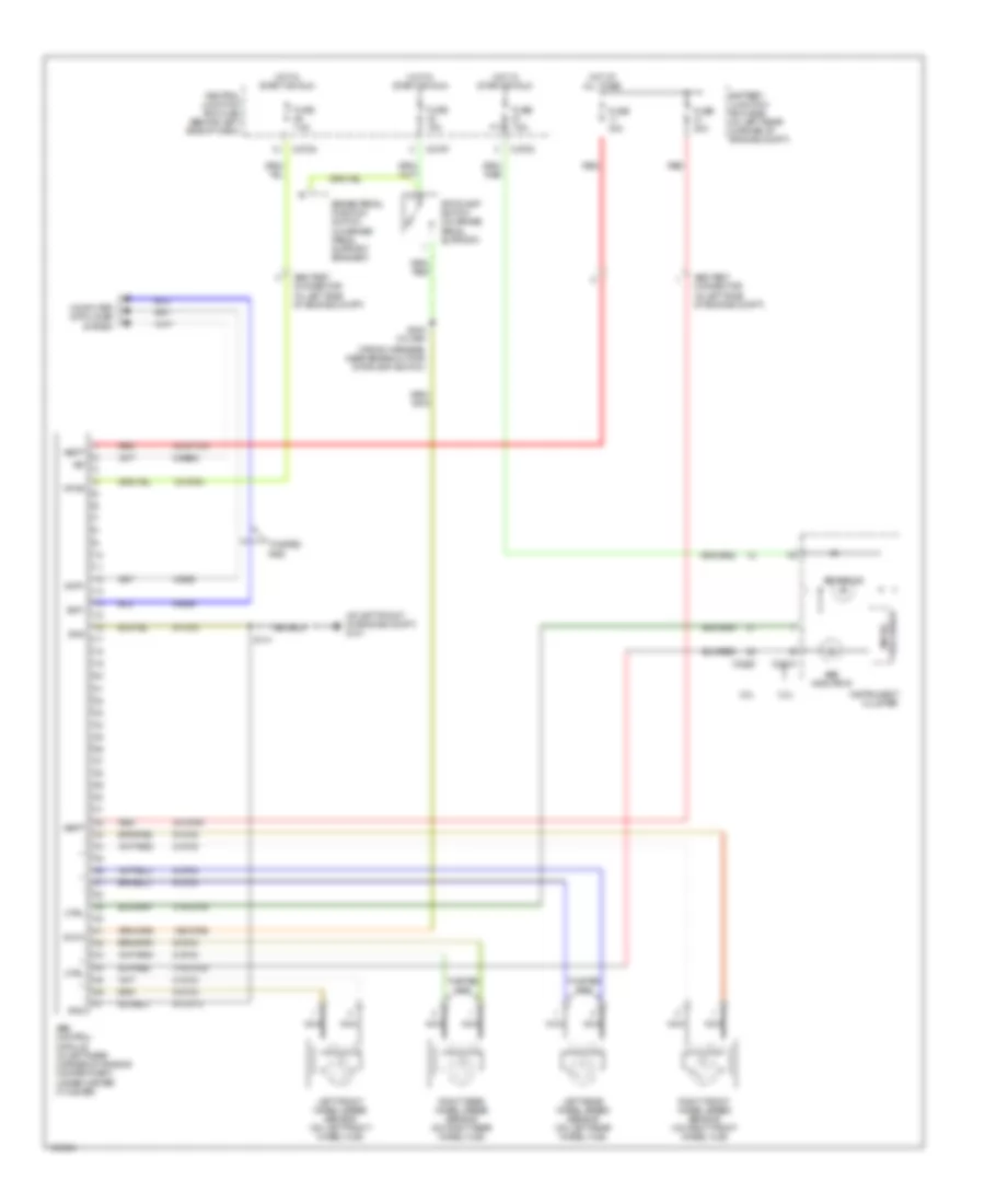
Anti-lock Brakes Wiring Diagram, without Traction Control for Ford Focus LX 2004
List of elements for Anti-lock Brakes Wiring Diagram, without Traction Control for Ford Focus LX 2004: