ANTI-LOCK BRAKES
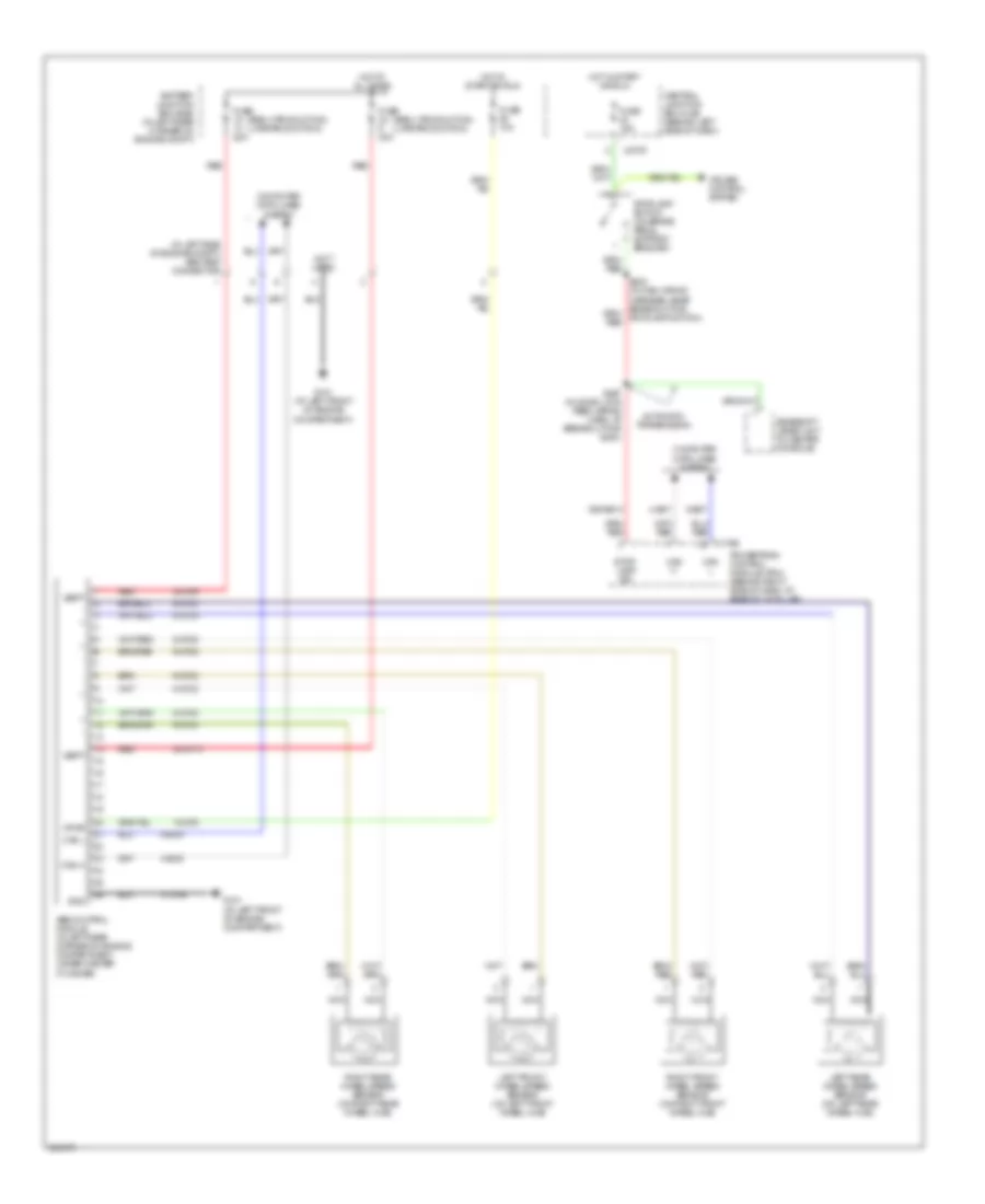
Anti-lock Brakes Wiring Diagram, with Traction Control for Ford Focus ZX5 SE 2006

List of elements for Anti-lock Brakes Wiring Diagram, with Traction Control for Ford Focus ZX5 SE 2006:
- (early production) (late production)
- (in left side of engine compt)
- (not used)
- 15-cf6
- 15s-re13
- 30-cf13
- 30-cf6
- 31-cf13
- 31-cf6
- 4-ec7
- 4-ec9
- 5-ec7
- 5-ec9
- 8-cf32
- 8-cf34
- 8-cf38
- 8-cf40
- 9-cf32
- 9-cf34
- 9-cf38
- 9-cf40
- 91s-cf54
- Abs control module (in left rear corner of engine compartment, under master cylinder)
- Abs test connector
- Automatic transmission
- Battery junction box (bjb) (in left rear corner of engine compt)
- Brake pedal position (on brake pedal support bracket)
- C175b
- C270f
- Can h
- Can l
- Central junction box (cjb) (behind left side of dash)
- Computer data lines system
- Fuse 10a
- Fuse 15a
- Fuse 20a
- Fuse 30a
- G101 (at left front of engine compt)
- G203 (at right "a" pillar)
- Gearshift lever unit (in center console)
- Gnd
- Hot at all times
- Hot in start or run
- Interior lights system
- Left front wheel speed sensor (on left front wheel hub)
- Left rear wheel speed sensor (on left rear wheel hub)
- Nca
- Powertrain control module (pcm) (behind right side of dash, at base of "a" pillar)
- Red
- Right front wheel speed sensor (on right front wheel hub)
- Right rear wheel speed sensor (on right rear wheel hub)
- S141
- S212
- S267 (in door lock feed wiring harn, at breakout for g200)
- Sig
- Stop- lamp sig
- Stoplamp switch (on brake pedal support bracket)
- Traction control system (tcs) disable switch
- Vbatt
- Vpwr
Anti-lock Brakes Wiring Diagram, without Traction Control for Ford Focus ZX5 SE 2006
List of elements for Anti-lock Brakes Wiring Diagram, without Traction Control for Ford Focus ZX5 SE 2006:
- (early production) (late production)
- (in left side of engine compt) abs test connector
- (not used)
- 15-cf6
- 15s-re13
- 30-cf13
- 30-cf6
- 31-cf6
- 4-ec7
- 4-ec9
- 5-ec7
- 5-ec9
- 8-cf32
- 8-cf34
- 8-cf38
- 8-cf40
- 9-cf32
- 9-cf34
- 9-cf38
- 9-cf40
- Abs control module (in left rear corner of engine compartment, under master cylinder)
- Automatic transmission
- Battery junction box (bjb) (in left rear corner of engine compt)
- C175b
- C270f
- Can h
- Can l
- Central junction box (cjb) (behind left side of dash)
- Computer data lines system
- Cruise control system
- Fuse 10a
- Fuse 15a
- Fuse 20a
- Fuse 30a
- G101 (at left front of engine compartment)
- Gearshift lever unit (in center console)
- Gnd
- Hot at all times
- Hot in start or run
- Left front wheel speed sensor (on left front wheel hub)
- Left rear wheel speed sensor (on left rear wheel hub)
- Nca
- Powertrain control module (pcm) (behind right side of dash, at base of "a" pillar)
- Red
- Right front wheel speed sensor (on right front wheel hub)
- Right rear wheel speed sensor (on right rear wheel hub)
- S267 (in door lock feed wiring harn, at breakout for g200)
- Stop- lamp sig
- Stoplamp switch (on brake pedal support bracket)
- Vbatt
- Vpwr