ANTI-LOCK BRAKES
Anti-lock Brakes Wiring Diagram for Ford Fusion SEL 2006
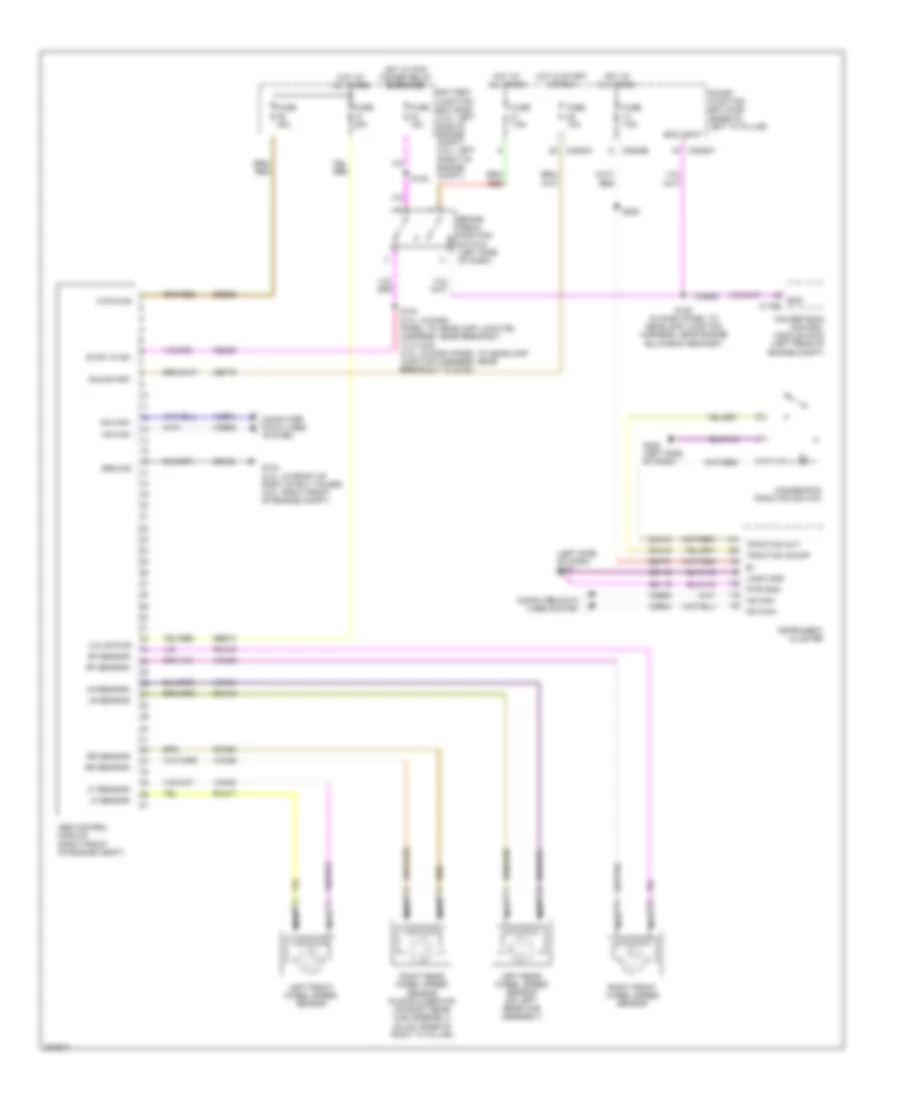
List of elements for Anti-lock Brakes Wiring Diagram for Ford Fusion SEL 2006:
- (left side of dash) g202
- Abs control module (right front of engine compt)
- Battery junction box (bjb) (2.3l: left side of engine compt) (3.0l: left front of engine compt)
- Boo
- Boo input
- Brake pedal position switch (left side of dash)
- C175b
- C2280a
- C2280b
- Cbp19
- Cca10
- Cca15
- Ccb08
- Ces09
- Computer data lines system
- Fuse 10a
- Fuse 15a
- Fuse 20a
- Fuse 40a
- Fuse 7.5a
- G104 (2.3l: in front of right strut tower) (3.0l: right front of engine compt)
- G202 (left side of dash)
- Gd116
- Gd123
- Ground
- Hazard/pad traction switch
- Hot at all times
- Hot in start or run
- Hot w/ pcm power relay energized
- Hs can+
- Hs can-
- Instrument cluster
- Left front wheel speed sensor
- Left rear wheel speed sensor (on left rear hub assembly)
- Lf sensor+
- Lf sensor-
- Logic gnd
- Lr sensor+
- Lr sensor-
- Mtr pwr
- Nca
- Powertrain control module (pcm) (left rear of engine compt)
- Pwr gnd
- Rca17
- Rca18
- Rca19
- Rca20
- Rf sensor+
- Rf sensor-
- Right front wheel speed sensor
- Right rear wheel speed sensor (fusion & zephyr: on right rear hub assembly) (milan: base of right "c" pillar)
- Rr sensor+
- Rr sensor-
- Run/start
- S120 (in dash panel to headlamp junction harness, near engine bulkhead grommet)
- S132
- S133 (2.3l: in dash panel to headlamp junction harness, near breakout to c1443) (3.0l: in dash panel to headlamp junction harness, near breakout to g103)
- S229
- Sbb10
- Sbb36
- Sbp07
- Smart junction box (sjb) (base of left "a" pillar)
- Stop lp sw
- Traction on/off
- Traction out
- Valve pwr
- Vca03
- Vca04
- Vca05
- Vca06
- Vdb04
- Vdb05
 English