ANTI-LOCK BRAKES
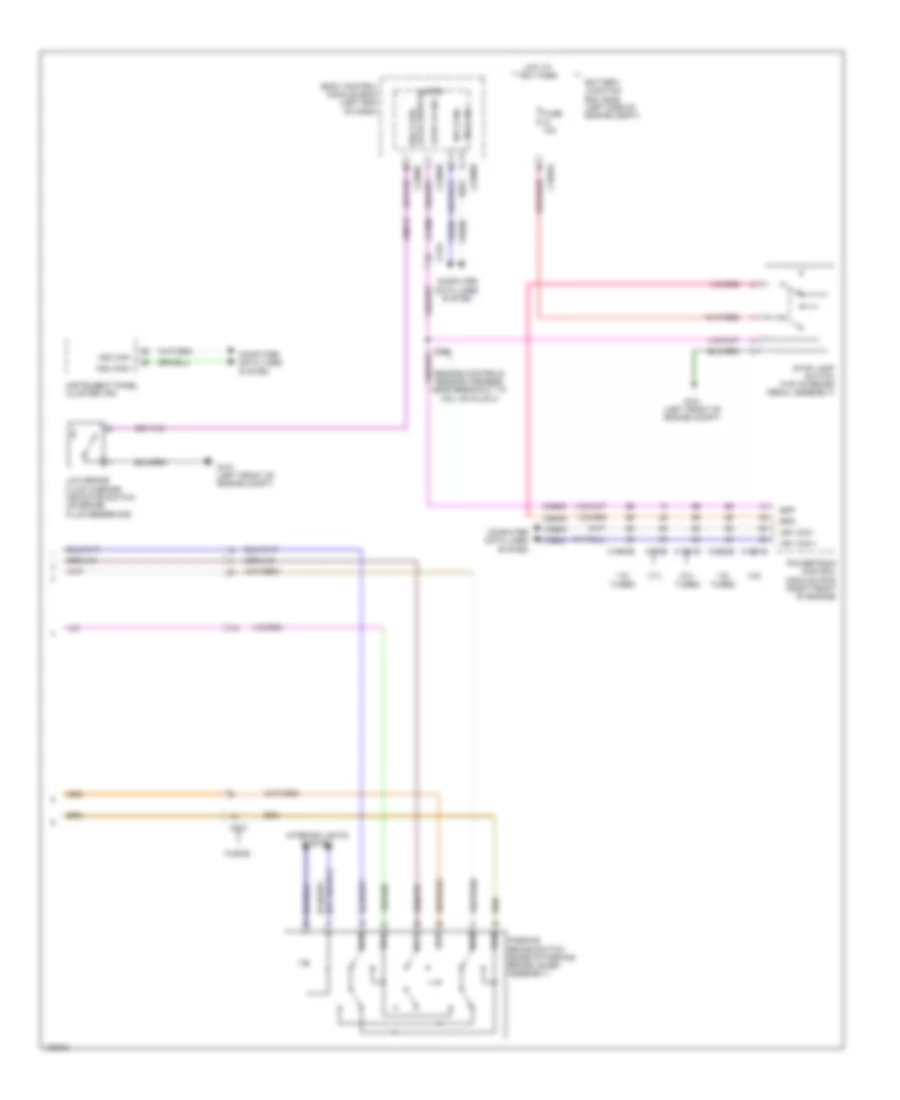
Anti-lock Brakes Wiring Diagram, Except Hybrid (1 of 2) for Ford Fusion Titanium 2014

List of elements for Anti-lock Brakes Wiring Diagram, Except Hybrid (1 of 2) for Ford Fusion Titanium 2014:
- Anti-lock brake system (abs) module (left rear of engine compt)
- Battery junction box (bjb) (left side of engine compt)
- Brake booster vacuum sensor (on brake booster)
- C1010
- C1035a
- C192
- C215
- C219
- C3050
- C3134
- C340
- Cbb25
- Ccb16
- Ccb17
- Ccb18
- Ccb19
- Ccb20
- Ccb21
- Ccb22
- Ccb23
- Ccb24
- Ccb25
- Computer data lines system
- Ebp sw1
- Ebp sw2
- Ebp sw3
- Ebp sw4
- Ebp sw5
- Ebp sw6
- Fuse 10a
- Fuse 30a
- Fuse 60a
- Fusion
- G102 (left front of engine compt)
- Gd121
- Gnd
- Hot at all times
- Hot in start or run
- Hs2 can+
- Hs2 can-
- Ign
- Lca37
- Left front wheel speed sensor (on left front hub assembly)
- Left parking brake actuator motor (in left rear wheelwell)
- Left rear wheel speed sensor (on left rear hub assembly)
- Lf sensor hi
- Lf sensor lo
- Lr sensor hi
- Lr sensor lo
- Mtr a epb lt
- Mtr a epb rt
- Mtr b epb lt
- Mtr b epb rt
- Nca
- Rca17
- Rca18
- Rca19
- Rca20
- Rca37
- Rf sensor hi
- Rf sensor lo
- Right front wheel speed sensor (on right front hub assembly)
- Right parking brake actuator motor (in right rear wheelwell)
- Right rear wheel speed sensor (on right rear hub assembly)
- Rr sensor hi
- Rr sensor lo
- Sbb69
- Sbb82
- Vac gnd
- Vac sense p
- Vac sig
- Vbatt
- Vca03
- Vca04
- Vca05
- Vca06
- Vca38
- Vdb25
- Vdb26
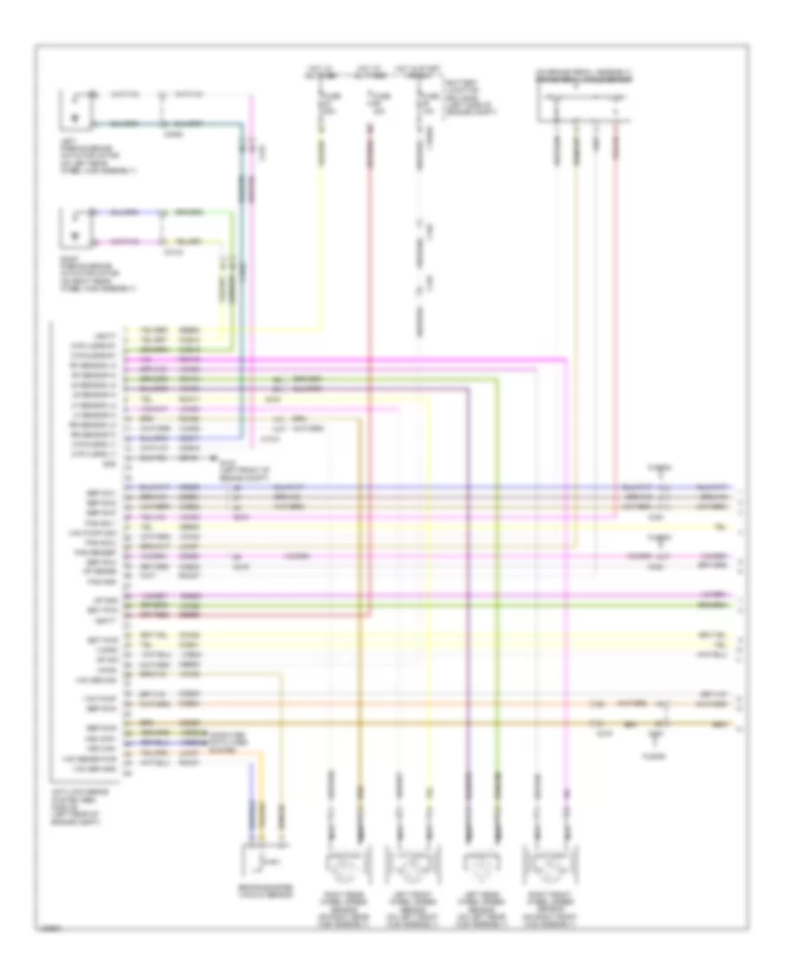
Anti-lock Brakes Wiring Diagram, Except Hybrid (2 of 2) for Ford Fusion Titanium 2014
List of elements for Anti-lock Brakes Wiring Diagram, Except Hybrid (2 of 2) for Ford Fusion Titanium 2014:
- (engine controls sensor harness, near breakout to coil on plug 3)
- 1.5l turbo
- 1.6l turbo
- 2.0l turbo
- 2.5l
- 3.7l
- Battery junction box (bjb) (left side of engine compt)
- Body control module (bcm) (left end of dash)
- Bpp
- Bps
- Brk fluid level switch
- C1035a
- C1232b
- C1381b
- C1551b
- C175b
- C1915b
- C210
- C219
- C2280b
- C2280c
- C2280h
- Ccb08
- Ces09
- Cmc19
- Computer data lines system
- Fuse 10a
- Fusion
- G101 (left front of engine compt)
- Hot at all times
- Hs1 can +
- Hs1 can -
- Hs1 can+
- Hs1 can-
- Hs3 can+
- Hs3 can-
- Instrument panel cluster (ipc)
- Interior lights system
- Low brake fluid warning indicator switch (on brake fluid reservoir)
- Micro
- Parking brake switch (base of parking brake lever assembly)
- Powertrain control module (pcm) (right front of engine)
- S204
- Stop lamp switch (top of brake pedal assembly)
- Stop lp sw
- Sw1
- Sw2
- Sw3
- Sw4
- Sw5
- Sw6
- Vdb04
- Vdb05
Anti-lock Brakes Wiring Diagram, Hybrid (1 of 2) for Ford Fusion Titanium 2014
List of elements for Anti-lock Brakes Wiring Diagram, Hybrid (1 of 2) for Ford Fusion Titanium 2014:
- (on brake pedal assembly) brake pedal angle sensor
- Anti-lock brake system (abs) module (left rear of engine compt)
- Battery junction box (bjb) (left side of engine compt)
- Brake booster vacuum sensor
- Bst pwm
- Bst pwr
- C1010
- C1035a
- C192
- C215
- C219
- C3050
- C3134
- C340
- Cbb25
- Cbb45
- Cca22
- Ccb16
- Ccb17
- Ccb18
- Ccb19
- Ccb20
- Ccb21
- Ccb22
- Ccb23
- Ccb24
- Ccb25
- Ccb30
- Ccb33
- Ccb41
- Computer data lines system
- Ebp sw1
- Ebp sw2
- Ebp sw3
- Ebp sw4
- Ebp sw5
- Ebp sw6
- Fuse 10a
- Fuse 30a
- Fuse 60a
- Fusion
- G102 (left front of engine compt)
- Gd121
- Gnd
- Hot at all times
- Hot in start or run
- Hs2 can+
- Hs2 can-
- Lca27
- Lca37
- Left front wheel speed sensor (on left front hub assembly)
- Left parking brake actuator motor (on left rear wheel hub assembly)
- Left rear wheel speed sensor (on left rear hub assembly)
- Lf sensor hi
- Lf sensor lo
- Lr sensor hi
- Lr sensor lo
- Mp gnd
- Mp sense
- Mp sig
- Mtr a epb lt
- Mtr a epb rt
- Mtr b epb lt
- Mtr b epb rt
- Nca
- Pas gnd
- Pas sensep
- Pas sig 1
- Pas sig 2
- Rca17
- Rca18
- Rca19
- Rca20
- Rca27
- Rca37
- Rcb33
- Rf sensor hi
- Rf sensor lo
- Right front wheel speed sensor (on right front hub assembly)
- Right parking brake actuator motor (on right rear wheel hub assembly)
- Right rear wheel speed sensor (on right rear hub assembly)
- Rr sensor hi
- Rr sensor lo
- Sbb69
- Sbb82
- Vac pump
- Vac pump mon
- Vac sen gnd
- Vac sen sig
- Vac sense pwr
- Vacrc
- Vbatt
- Vca03
- Vca04
- Vca05
- Vca06
- Vca22
- Vca30
- Vca38
- Vca43
- Vcb34
- Vdb25
- Vdb26
- Vpwr
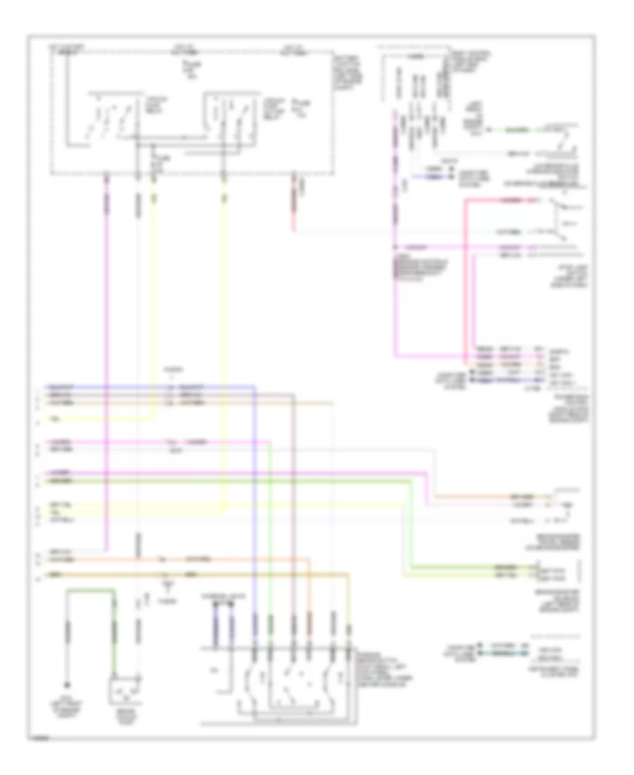
Anti-lock Brakes Wiring Diagram, Hybrid (2 of 2) for Ford Fusion Titanium 2014
List of elements for Anti-lock Brakes Wiring Diagram, Hybrid (2 of 2) for Ford Fusion Titanium 2014:
- (left front of engine compt) g101
- Battery junction box (bjb) (left side of engine compt)
- Body control module (bcm) (left end of dash)
- Bpp
- Bps
- Brake booster solenoid (left rear of engine compt)
- Brake booster travel sensor (on brake booster)
- Brake vacuum pump
- Brk fluid level switch
- Bst pwm
- Bst pwr
- C1035a
- C146
- C175b
- C210
- C219
- C2280b
- C2280c
- C2280h
- Ccb08
- Ces09
- Cluster (ipc)
- Cmc19
- Computer
- Computer data lines system
- Data lines
- Fuse 10a
- Fuse 40a
- Fuse 5a
- Fusion
- G101 (left front of engine compt)
- Hot at all times
- Hot in start or run
- Hs1 can +
- Hs1 can -
- Hs1 can+
- Hs1 can-
- Hs3 can+
- Hs3 can-
- Instrument panel
- Interior lights system
- Low brake fluid warning indicator switch (on brake fluid reservoir)
- Micro
- Parking brake switch (foot pedal: left kick panel) (hand lever: under center console)
- Powertrain control module (pcm) (right rear of engine compt)
- Re406
- S204 (engine controls sensor harness, near breakout to c1010)
- Sigrtn
- Stop lamp switch (under left side of dash)
- Stop lp sw
- Sw1
- Sw2
- Sw3
- Sw4
- Sw5
- Sw6
- System
- Vacuum pump cut-off relay
- Vacuum pump relay
- Vdb04
- Vdb05