ANTI-LOCK BRAKES
Anti-lock Brake Wiring Diagrams for Ford Mustang 1995
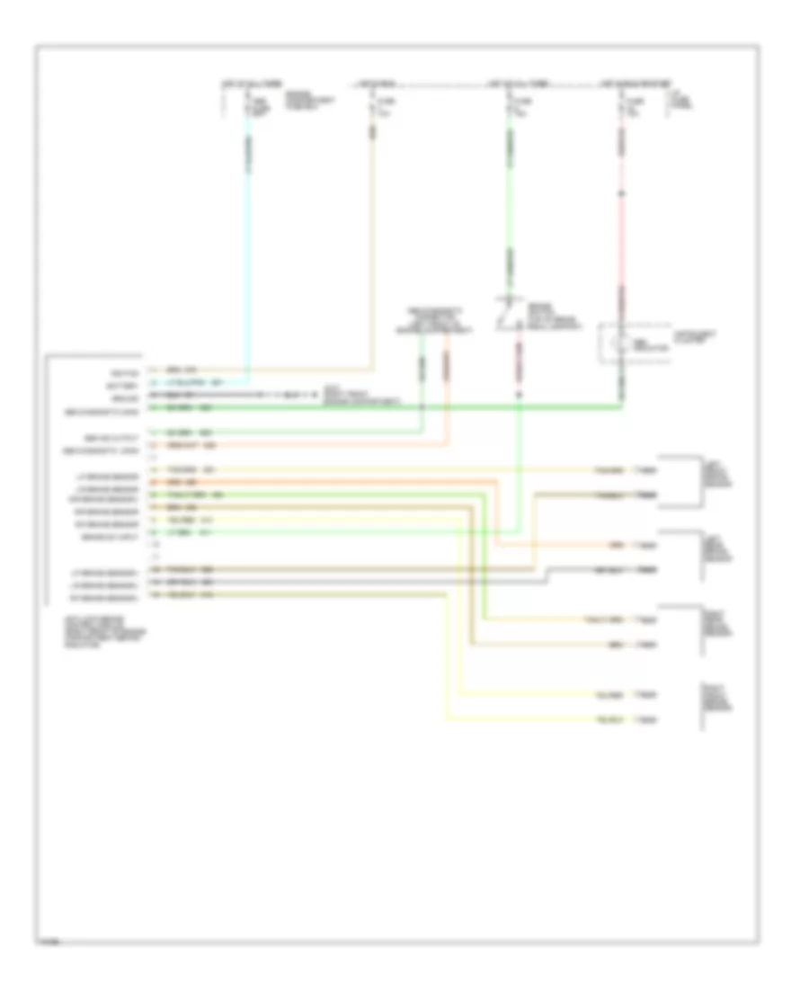
List of elements for Anti-lock Brake Wiring Diagrams for Ford Mustang 1995:
- Abs diagnostic conn
- Abs diagnostic conn
- Abs diagnostic connector (left front of engine compartment)
- Abs fuse 60a
- Abs ind output
- Abs indicator
- Anti-lock brake control module (right front of engine compartment behind radiator)
- Battery
- Brake sw input
- Brake switch (top of brake pedal support)
- Engine compartment fuse box
- Fuse 10a
- Fuse 15a
- G101 (right front engine compartment)
- Ground
- Hot at all times
- Hot in run
- Hot in run or start
- I/p fuse panel
- Ignition
- Instrument cluster
- L/f brake sensor
- L/f brake sensor(-)
- L/r brake sensor
- L/r brake sensor(-)
- Left front brake sensor
- Left rear brake sensor
- Nca
- R/f brake sensor
- R/f brake sensor(-)
- R/r brake sensor
- R/r brake sensor(-)
- Right front brake sensor
- Right rear brake sensor
 English