ANTI-LOCK BRAKES
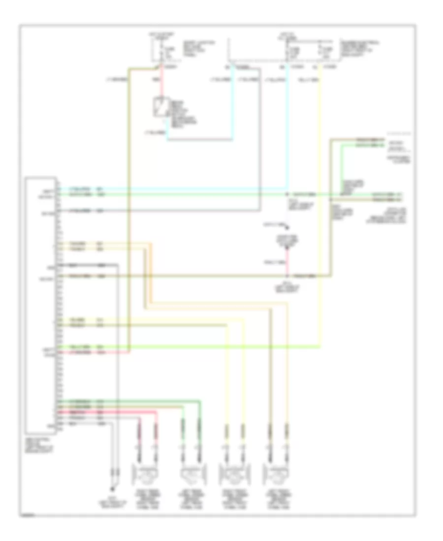
Anti-lock Brakes Wiring Diagram for Ford Mustang 2005
List of elements for Anti-lock Brakes Wiring Diagram for Ford Mustang 2005:
- (main harn, center of dash) s208
- Abs control module (left front of engine compt)
- Brake pedal position switch (on bracket, above brake pedal)
- Bussed electrical center (bec) (right front of eng compt)
- C1035a
- C1035d
- C2280h
- Computer data lines system
- Data link connector (behind dash, left of steering column)
- Fuse 10a
- Fuse f1.65 30a
- Fuse f1.7 40a
- G101 (left front of eng compt)
- Gnd
- Hot at all times
- Hot in start or run
- Hs can +
- Hs can -
- Instrument cluster
- Left front wheel speed sensor (left front wheel hub)
- Left rear wheel speed sensor (left rear wheel hub)
- Nca
- Red
- Red/pnk
- Right front wheel speed sensor (right front wheel hub)
- Right rear wheel speed sensor (right rear wheel hub)
- S113 (left side of eng compt)
- S114 (left side of eng compt)
- S207 (main harn, center of dash)
- Smart junction box (sjb) (right kick panel)
- Sw sig
- Vbatt
- Vpwr
 English