ANTI-LOCK BRAKES
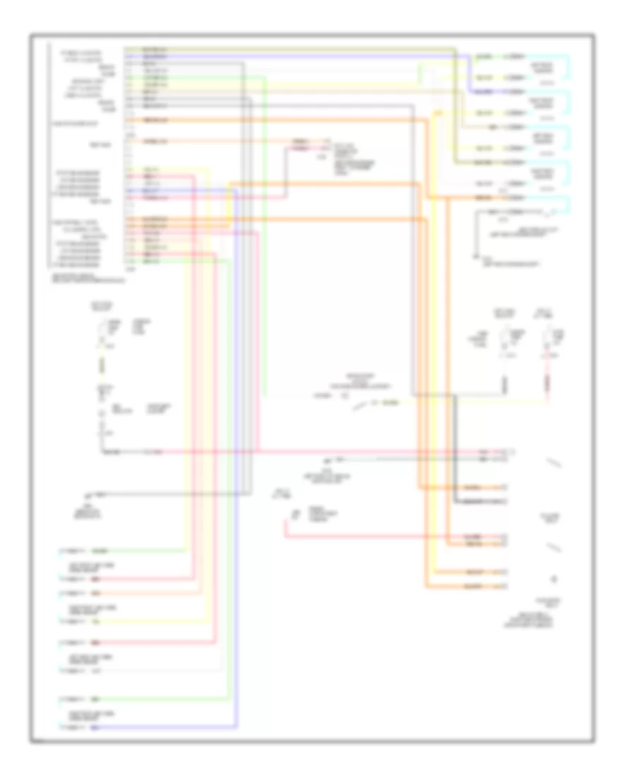
Anti-lock Brake Wiring Diagrams for Ford Probe SE 1996
List of elements for Anti-lock Brake Wiring Diagrams for Ford Probe SE 1996:
- (behind top
- (left front of vehicle,
- (left rear of engine compt)
- (left rear of engine compt.)
- (left side of engine
- (near left side of steering column)
- (partial)
- (right side of engine
- (top of brake pedal support)
- 15a
- 20a
- 60a
- Abs
- Abs control module
- Abs hydraulic unit
- Abs ind ctrl
- Abs main relay
- All times
- Apron)
- Brake on/off
- Brake sw input
- C135
- C173
- C174
- C214
- C215
- C216
- C222
- C223
- C241
- Center of i/p)
- Cluster
- Compartment
- Compartment fuse box)
- Compt., on fender
- Connector
- Data link
- Engine
- Fail safe
- Fail safe rly ctrl
- Fuse
- Fuse box
- G102
- G106
- G206
- Ground
- Hot at
- Hot in run
- Indicator
- Instrument
- Interior
- L fnt brake sensor
- L fnt valve ctrl
- L rear brake sensor
- L rear valve ctrl
- Left front
- Left front abs wheel
- Left rear
- Left rear abs wheel
- Meter
- Nca
- Near fog lamp)
- Or start
- Panel
- Pnk
- Pnk 408
- Power
- Pump motor
- Pump mtr power input
- Pump mtr relay cntrl
- Red
- Red 411
- Red 415
- Relay
- Right front
- Right front abs wheel
- Right rear
- Right rear abs wheel
- Rt fnt brake sensor
- Rt fnt valve ctrl
- Rt rear brake sensor
- Rt rear valve ctrl
- Solenoid
- Speed sensor
- Stop
- Switch
- Test conn
 English