ANTI-LOCK BRAKES
Anti-lock Brake Wiring Diagrams for Ford Ranger 2002
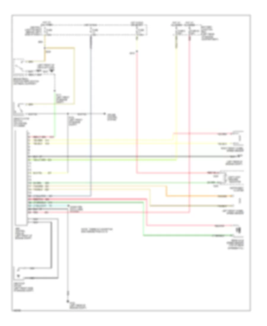
List of elements for Anti-lock Brake Wiring Diagrams for Ford Ranger 2002:
- (left front of vehicle floor) g205
- (left rear of engine compt)
- Abs control module (left front of engine compt)
- Abs pump motor (left front side of engine compt)
- Anti-lock brakes indicator
- Battery junction box (left rear of engine compartment)
- Brake pedal position (bpp) switch (on pedal support)
- C220
- Central junction box (behind left side of dash)
- Computer data lines system
- Cruise control system
- Deactivator switch (on master cylinder)
- Differential)
- Fuse 10a
- Fuse 28 30a
- Fuse 6 50a
- Fuse 7.5a
- G102
- G102 (left rear of engine compt)
- Hot at all times
- Hot in run
- Hot in run or start
- Instrument cluster
- Left front wheel speed sensor
- Nca
- Note: there is a shorting bar across pins 8 & 16
- Ohms
- Rear axle speed sensor (top of rear
- Red
- Red/pnk
- Right front wheel speed sensor
- S103 (left front of engine compt)
- S117 (left front of engine compt)
- S218
- S238
 English