ANTI-LOCK BRAKES
Anti-lock Brakes Wiring Diagram for Ford Ranger 2004
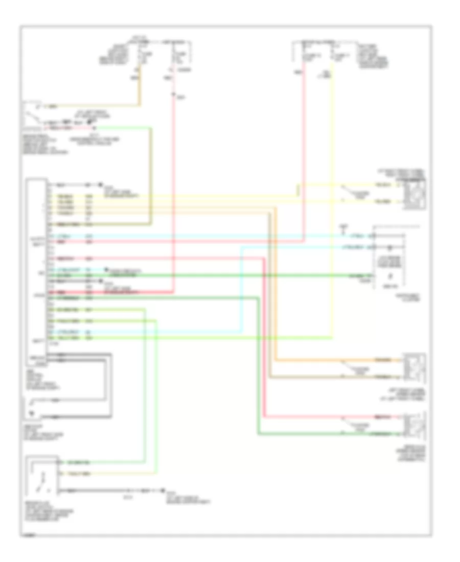
List of elements for Anti-lock Brakes Wiring Diagram for Ford Ranger 2004:
- (at left front of vehicle floor) g205
- (at right front wheel) right front wheel speed sensor
- 4wd
- 4x4 sta
- Abs control module (on left front of engine compt)
- Abs ind
- Abs pump motor (at left front side of engine compt)
- Battery junction box (bjb) (at left rear side of engine compartment)
- Brake fluid level switch (at left rear of engine compartment, brake fluid reservoir)
- Brake pedal position switch (behind left side of dash, on brake pedal support)
- C135
- C220b
- C2280b
- Computer data lines system
- Fuse 10a
- Fuse 15 30a
- Fuse 17 40a
- Fuse 5a
- G102 (at left side of engine compt)
- G103 (at left side of engine compartment)
- Ground
- Hot at all times
- Hot in run
- Instrument cluster
- Iso
- Left front wheel speed sensor (at left front wheel)
- Low brake fluid level/ park brake
- Nca
- Pwr
- Rear axle speed sensor (top of rear differential)
- Red
- Red red
- Red/pnk
- S110
- S117 (near breakout for abs control module)
- S221
- Smart junction box (sjb) (behind right side of dash)
- Twisted pair
- Vbatt
- Vpwr
 English