ANTI-LOCK BRAKES
Anti-lock Brakes Wiring Diagram for Ford Ranger 2007
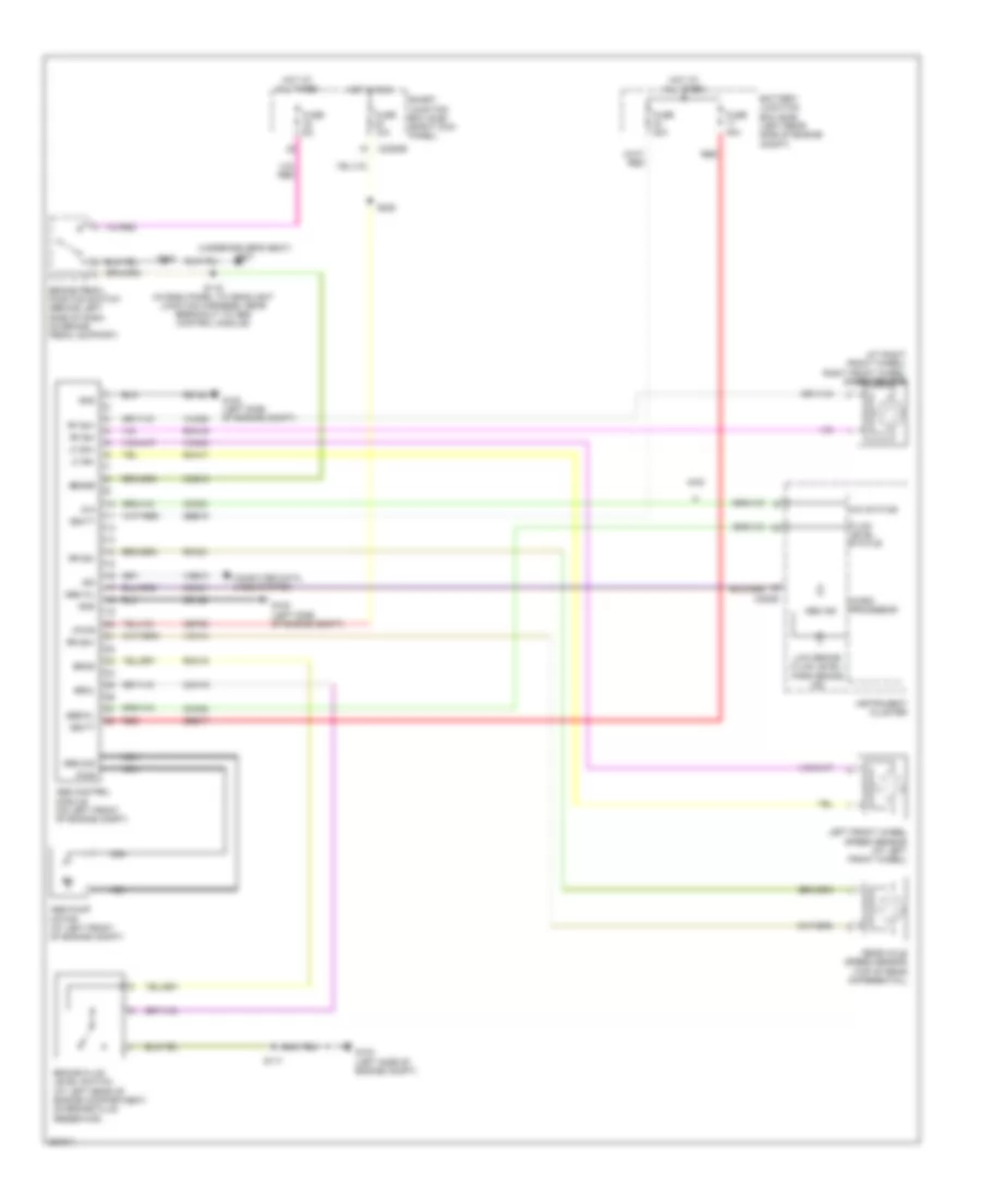
List of elements for Anti-lock Brakes Wiring Diagram for Ford Ranger 2007:
- (at right front wheel) right front wheel speed sensor
- (under driver's seat) g301
- 4wd
- 4x4
- 4x4 status
- Abs control module (on left front of engine compt)
- Abs ind
- Abs pump motor (at left front of engine compt)
- Abs wl
- Battery junction box (bjb) (left rear side of engine compt)
- Brake fluid level switch (at left rear of engine compartment, on brake fluid reservoir)
- Brake pedal position switch (behind left side of dash, on brake pedal support)
- Brkl
- Brks
- C220b
- C2280b
- Cbp20
- Cca01
- Cca02
- Ccb15
- Ccf23
- Cmc19
- Computer data lines system
- Ebdwl
- Fluid level status
- Fuse 10a
- Fuse 30a
- Fuse 40a
- Fuse 5a
- G102 (left side of engine compt)
- G103 (left side of engine compt)
- Gd122
- Gnd
- Ground
- Hot at all times
- Hot in run
- Instrument cluster
- Iso
- Left front wheel speed sensor (at left front wheel)
- Lf sn+
- Lf sn-
- Low brake fluid level/ park brake ind
- Micro- processor
- Nca
- Pwr
- Rca17
- Rca19
- Rca21
- Rear axle speed sensor (top of rear differential)
- Red
- Rf sn+
- Rf sn-
- Rmc19
- Rr sn+
- Rr sn-
- S117
- S119 (in dash panel to headlight junction harness, near breakout to abs control module)
- S208
- S220
- Sbb15
- Sbb17
- Sense
- Smart junction box (sjb) (right kick panel)
- Vbatt
- Vca03
- Vca05
- Vca14
- Vdb10
- Vpwr
 English