ANTI-LOCK BRAKES
Anti-lock Brakes Wiring Diagram, with Stripped Chassis for Ford RV Cutaway E350 Super Duty 2004

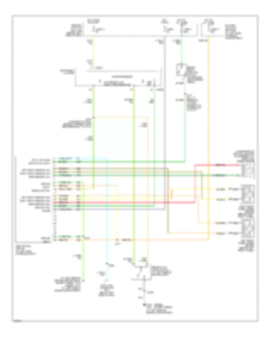
List of elements for Anti-lock Brakes Wiring Diagram, with Stripped Chassis for Ford RV Cutaway E350 Super Duty 2004:
- (at left rear of engine compartment) g105
- (diesel)
- (except diesel)
- (under rear of vehicle, mounted on differential) rear axle speed sensor
- Abs control module (at left side of engine compt)
- Abs ind
- Abs ind ctrl
- Battery junction box (bjb) (at left side of engine compartment)
- Bpp switch input
- Brake fluid level switch (at left rear of engine compt)
- Brake ind ctrl
- Brake pedal position switch (on bracket, above brake pedal)
- C220a
- C220b
- Central junction box (cjb) (behind left side of dash)
- Data link conn
- Data link connector (dlc) (behind left side of dash)
- Fuse 1 5a
- Fuse 11 15a
- Fuse 11 60a
- Fuse 14 5a
- G114 (at rear center of engine compt)
- G121 (at left side of engine compartment)
- Ground
- Hot at all times
- Hot in run
- Hot in run or start
- Instrument cluster
- Left front sensor high
- Left front sensor low
- Left front wheel speed sensor (behind left front wheel)
- Low brake fluid level/ park brake ind
- Microprocessor
- Nca
- Power
- Rear sensor high
- Rear sensor low
- Red/pnk
- Right front sensor high
- Right front sensor low
- Right front wheel speed sensor (behind right front wheel)
- S125 (in engine control sensor harness, in breakout to c219)
- S147
- S177
- S199
- S220 (diesel: in breakout to c219) (except diesel: in breakout to c110)
- Vbatt
Anti-lock Brakes Wiring Diagram, without Stripped Chassis for Ford RV Cutaway E350 Super Duty 2004
List of elements for Anti-lock Brakes Wiring Diagram, without Stripped Chassis for Ford RV Cutaway E350 Super Duty 2004:
- (at left rear of engine compartment)
- (at left rear of engine compartment) g105
- (diesel)
- (diesel) (except diesel)
- (except diesel)
- (under rear of vehicle, mounted on differential) rear axle speed sensor
- Abs control module (at left side of engine compt)
- Abs ind
- Abs ind ctrl
- Battery junction box (bjb) (at left side of engine compartment)
- Bpp switch input
- Brake fluid level switch (at left rear of engine compt)
- Brake ind ctrl
- Brake pedal position switch (on bracket, above brake pedal)
- C220a
- C220b
- Central junction box (cjb) (behind left side of dash)
- Data link conn
- Data link connector (dlc) (below left side of dash)
- Fuse 1 5a
- Fuse 11 15a
- Fuse 11 60a
- Fuse 14 5a
- G100 g105
- G121 (at left side of engine compartment)
- Ground
- Hot at all times
- Hot in run
- Hot in run or start
- Instrument cluster
- Left front sensor high
- Left front sensor low
- Left front wheel speed sensor (behind left front wheel)
- Low brake fluid level/ park brake ind
- Microprocessor
- Nca
- Power
- Rear sensor high
- Rear sensor low
- Red/pnk
- Right front sensor high
- Right front sensor low
- Right front wheel speed sensor (behind right front wheel)
- S1005
- S147
- S149 (in engine control sensor harness, near near breakout to c110)
- S174 (6.0l: in breakout to c219) (except 6.0l: in breakout to c110)
- S177
- S226
- Vbatt