ANTI-LOCK BRAKES
Anti-lock Brake Wiring Diagrams for Ford Taurus LX 1999
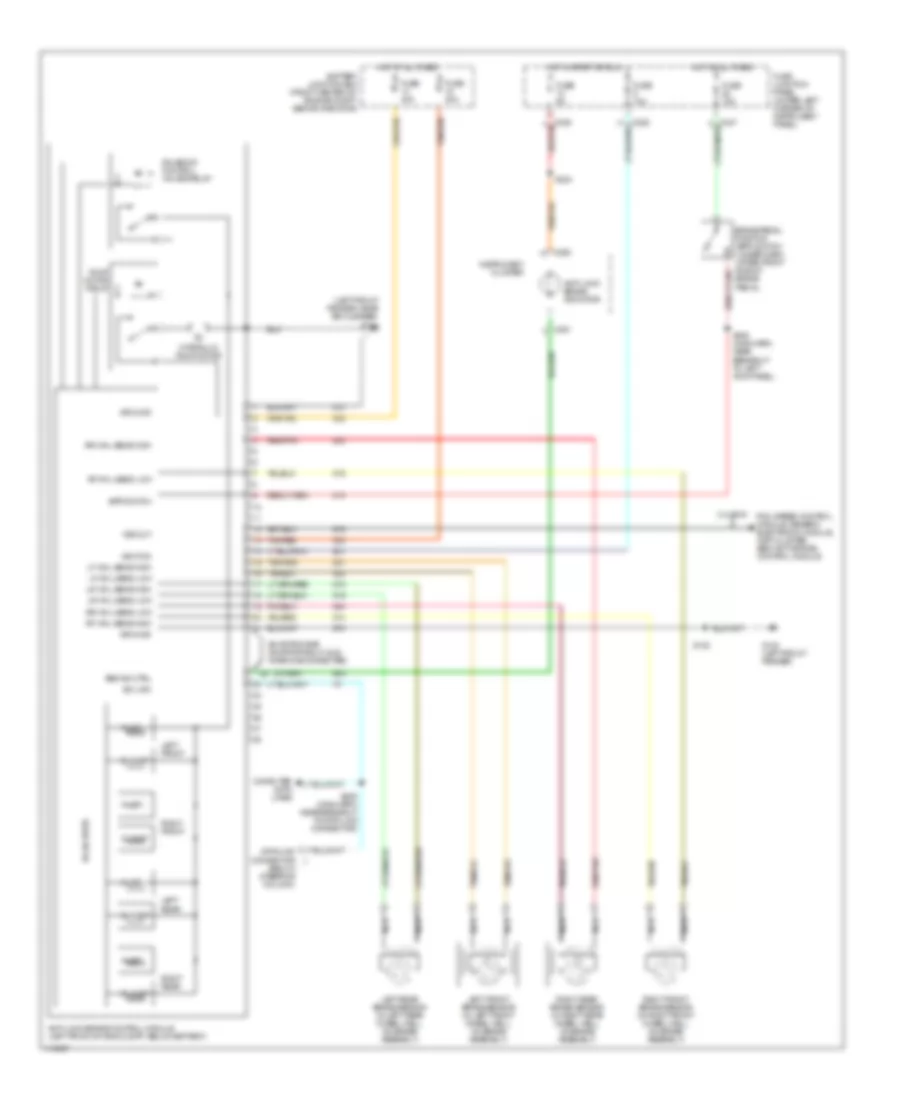
List of elements for Anti-lock Brake Wiring Diagrams for Ford Taurus LX 1999:
- (below steering column)
- (left front fender, near air cleaner)
- 3.4l sho
- Abs ind ctrl
- Anti-lock brake control module (left front of eng compt, below battery)
- Anti-lock brake indicator
- Battery junction box (front center of engine compt, behind radiator)
- Bpp switch
- Brake pedal position (bpp) switch (under dash, upper front side of brake pedal)
- C250
- C251
- Computer data lines
- Fuse 10a
- Fuse 15a
- Fuse 30a
- Fuse 40a
- Fuse 5a
- Fuse junction panel (under left corner of instrument panel)
- G100 (left front fender)
- G104
- Ground
- Hot at all times
- Hot in start or run
- Hydraulic pump motor
- Ignition
- Inlet
- Instrument cluster
- Iso link
- Left front
- Left front brake sensor (in left front wheel well, on brake assembly)
- Left rear
- Left rear brake sensor (in left rear wheel well, on brake assembly)
- Lf whl sens high
- Lf whl sens low
- Lr whl sens high
- Lr whl sens low
- Nca
- Outlet
- Pcm, speed control module, generic electronic module, inst cluster, semi-active ride control module
- Pump motor relay
- Red/pnk
- Rf whl sens high
- Rf whl sens low
- Right front
- Right front brake sensor (in right front wheel well, on brake assembly)
- Right rear
- Right rear brake sensor (in right rear wheel well, on brake assembly)
- Rr whl sens high
- Rr whl sens low
- S120
- S224
- S225 (main harn, near breakout to data link connector)
- S308 (main harn, near breakout to left kick panel)
- Shorting bar (shorts pins 21 & 22 when disconnected)
- Solenoid control valves relay
- Solid state
- Tan/red
- Vss out
 English