ANTI-LOCK BRAKES
Anti-lock Brakes Wiring Diagram, with Traction Control for Ford Taurus SEL 2006

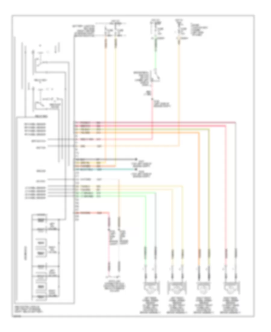
List of elements for Anti-lock Brakes Wiring Diagram, with Traction Control for Ford Taurus SEL 2006:
- Abs control module (left front of engine compt, below battery)
- Abs module
- Abs pump motor
- Adaptive damping ind
- Battery junction box (front center of engine compt, behind radiator)
- Bpp switch
- Brake assembly)
- Brake pedal position switch (under left side of dash)
- C2280a
- C2280b
- C2280c
- Data link connector (dlc) (mounted on dash, below steering column)
- Front
- Fuse 10a
- Fuse 15a
- Fuse 20a
- Fuse 40a
- G107 (top left side of engine compt)
- G108 (top left side of engine compt)
- G201 (behind center of dash)
- Ground
- Hot at all times
- Hot in run
- Hot in run or start
- Hs can+
- Hs can-
- Ignition
- Illum
- Instrument cluster
- Interior lights system
- Left dump valves
- Left front wheel speed sensor (in left front wheelwell, mounted on brake assembly)
- Left iso valves
- Left rear wheel speed sensor (in left rear wheelwell, mounted on brake assembly)
- Lf wheel sensor
- Lr wheel sensor
- Microprocessor
- Nca
- Rear
- Red/pnk
- Relay box
- Rf wheel sensor
- Right dump valves
- Right front wheel speed sensor (in right front wheelwell, mounted on
- Right iso valves
- Right rear wheel speed sensor (in right rear wheelwell, mounted on
- Rr wheel sensor
- S129 (left side of engine compt)
- S130 (left side of engine compt)
- S136 (left side of engine compt)
- S207
- S209
- S212
- Smart junction box (under left side of dash)
- Tan/red
- Traction control off
- Traction control switch
- Volt
- Vpwr
Anti-lock Brakes Wiring Diagram, without Traction Control for Ford Taurus SEL 2006
List of elements for Anti-lock Brakes Wiring Diagram, without Traction Control for Ford Taurus SEL 2006:
- Abs control module (left front of engine compt, below battery)
- Abs module
- Abs pump motor
- Battery junction box (bjb) (front center of engine compt, behind radiator)
- Bpp switch
- Brake pedal position switch (under left side of dash)
- C2280a
- C2280c
- Data link connector (dlc) (mounted on dash, below steering column)
- Front
- Fuse 10a
- Fuse 15a
- Fuse 20a
- Fuse 40a
- G107 (top left side of engine compt)
- G108 (top left side of engine compt)
- Ground
- Hot at all times
- Hot in run
- Hs can+
- Hs can-
- Ignition
- Left dump valves
- Left front wheel speed sensor (in left front wheelwell, mounted on brake assembly)
- Left iso valves
- Left rear wheel speed sensor (in left rear wheelwell, mounted on brake assembly)
- Lf wheel sensor
- Lr wheel sensor
- Nca
- Rear
- Red/pnk
- Relay box
- Rf wheel sensor
- Right dump valves
- Right front wheel speed sensor (in right front wheelwell, mounted on brake assembly)
- Right iso valves
- Right rear wheel speed sensor (in right rear wheelwell, mounted on brake assembly)
- Rr wheel sensor
- S129 (left side of engine compt)
- S130 (left side of engine compt)
- S136 (left side of engine compt)
- Smart junction box (under left side of dash)
- Tan/red