ANTI-LOCK BRAKES
Anti-lock Brake Wiring Diagrams for Ford Thunderbird Super Coupe 1995
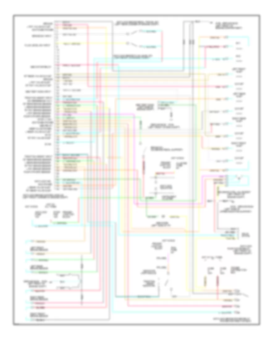
List of elements for Anti-lock Brake Wiring Diagrams for Ford Thunderbird Super Coupe 1995:
- (ground bus)
- (left front corner of engine compt)
- (left front of
- (left front of
- (left front of eng compt)
- (left front of engine compt)
- (left rear corner of engine compt)
- (left side of
- (left side of i/p)
- (on brake pedal support)
- (power distribution box)
- 10a
- 15a
- 20a
- 40a
- 87a
- Abs diode
- Abs motor relay
- Abs relay
- Abs test conn
- Abs test conn input
- All times
- Anti/lock
- Anti/lock brake control module
- Anti/lock brake fluid level sw
- Anti/lock brake pedal travel sw
- Anti/lock brake power relay
- Anti/lock ind
- Assist
- Block
- Box
- Brake sensor
- Brake sw
- Brake sw input
- Cluster
- Distribution
- Engine compartment)
- Engine compt)
- Fluid level sw input
- Fuse
- G108
- Ground
- Haz
- Hot at
- Hot at all times
- Hot in run
- Indicator
- Inlet
- Instrument
- Junction
- Keep alive power
- L fnt brake sensor
- L fnt valve inlet
- L fnt valve outlet
- L rear brake sensor
- L rear valve inlet
- L rear valve outlet
- Lamp module
- Left front
- Left front of
- Left rear
- Outlet
- Pnk
- Pnk 498
- Power
- Primary
- Pump motor relay
- Pump mtr spd sensor
- Red/pnk
- Red/pnk 523
- Right front
- Right rear
- Rt fnt brake sensor
- Rt fnt valve inlet
- Rt fnt valve outlet
- Rt rear brake sensor
- Rt rear valve inlet
- Rt rear valve outlet
- Run
- Run power
- Solenoid ctrl valve body
- Solid
- State
- Stop lt sw
- Stop/
- Sv #1
- Sv #2
- Sv1
- Sv2
- Sw reference volt
- Switched power
- Tan
- Tan 495
- Tan/red
- Tan/red 510
- Tan/red 533
- Traction
- Traction assist input
- Upper radiator support)
 English