ANTI-LOCK BRAKES
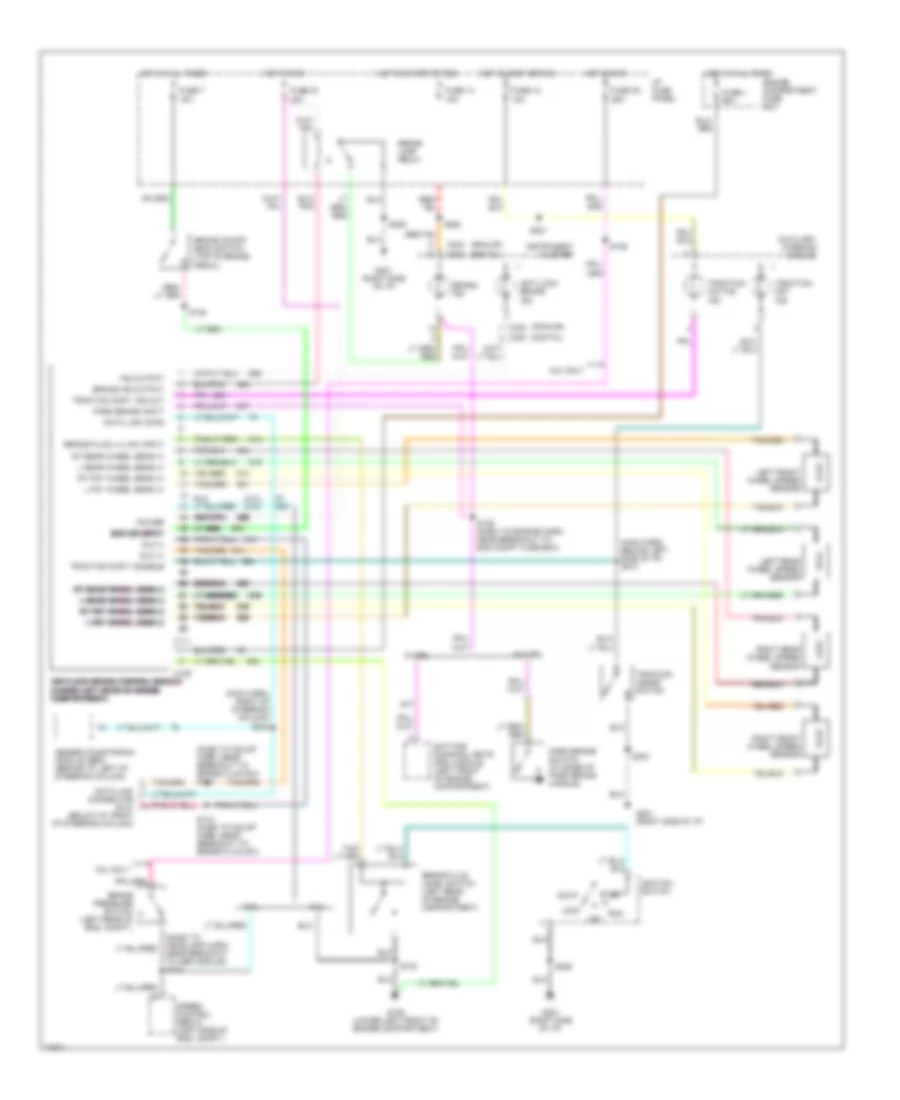
Anti-lock Brake Wiring Diagrams for Ford Windstar LX 1997
List of elements for Anti-lock Brake Wiring Diagrams for Ford Windstar LX 1997:
-
- (3.0l) (3.8l)
- (analog)
- (dash to hdlmp harn, near breakout to brake fluid sw) s143
- (dash to headlamp harn, near breakout to abs module) s142
- (digital)
- (main harn, behind left side of i/p) s210
- (main harn, right of steering column) s242
- 3.0l
- 3.8l
- 3.8l only
- Acc
- Anti-lock brake control module anti-lock brake control module anti-lock brake control module anti-lock brake control module anti-lock brake control module (lower left rear of engine (lower left rear of engine (lower left rear of engine (lower left rear of engine (lower left rear of engine compartment) compartment) compartment) compartment) compartment)
- Anti-lock brake ind
- Auxiliary warning module
- Boo sw input boo sw input boo sw input boo sw input boo sw input
- Brake fluid level switch (left rear of engine compartment)
- Brake fluid lvl sw input
- Brake ind
- Brake ind output
- Brake lamp relay
- Brake on/off (boo) switch (top of brake pedal)
- Brake pressure switch (left rear of eng. compt.)
- C105
- C111
- C202
- C240
- Data link conn
- Data link connector (dlc) (below i/p, right of steering column)
- Daytime running lights (drl) module (left front of engine compartment)
- Dlc (+)
- Dlc (-)
- Engine compartment fuse box
- Fuse 12 10a
- Fuse 14 15a
- Fuse 30 25a
- Fuse 33 15a
- Fuse 7 15a
- Fuse l 60a
- G106 (lower left front of engine compartment)
- G201 (right side of i/p)
- Generic electronic module (gem) (behind i/p, left of steering column)
- Hot at all times
- Hot in accy or run
- Hot in run
- Hot in start or run
- I/p fuse panel
- Ignition switch
- Ind output
- Instrument cluster
- L fnt wheel sens (+)
- L fnt wheel sens (-) l fnt wheel sens (-) l fnt wheel sens (-) l fnt wheel sens (-) l fnt wheel sens (-)
- L rear wheel sens (+)
- L rear wheel sens (-) l rear wheel sens (-) l rear wheel sens (-) l rear wheel sens (-) l rear wheel sens (-)
- Left front wheel speed sensor
- Left rear wheel speed sensor
- Lock
- Off
- Park brake input
- Park brake switch (at base of park brake handle)
- Power
- Right front wheel speed sensor
- Right rear wheel speed sensor
- Rt fnt wheel sens (+)
- Rt fnt wheel sens (-) rt fnt wheel sens (-) rt fnt wheel sens (-) rt fnt wheel sens (-) rt fnt wheel sens (-)
- Rt rear wheel sens (+)
- Rt rear wheel sens (-) rt rear wheel sens (-) rt rear wheel sens (-) rt rear wheel sens (-) rt rear wheel sens (-)
- Run
- S103
- S106
- S128
- S129 (dash to engine harn, near breakout to eng compt fuse box)
- S144 (dash to hdlmp harn, near breakout to brake fluid sw)
- S203
- S205
- S220
- S221
- Speed control servo (left side of eng. compt.)
- Start
- Traction active ind
- Traction assist switch
- Traction cont. disable
- Traction cont. ind out
- Traction off ind
- W/ drl
- W/o drl
 English