ANTI-LOCK BRAKES
Anti-lock Brakes Wiring Diagram, with Vehicle Speed Enhancement Stability (1 of 2) for GMC Yukon XL C1500 2004

List of elements for Anti-lock Brakes Wiring Diagram, with Vehicle Speed Enhancement Stability (1 of 2) for GMC Yukon XL C1500 2004:
- (not used)
- (on left rear
- A c9
- Abs fuse 60a
- Abs/tcs class 2 serial data
- B c9
- Battery (+)
- Brake fluid level sensor sig
- Brake fuse 10a
- Brake in
- C12
- C5 c1
- Control module (ebcm)
- Del torque
- Delivered torque signal
- Electronic brake
- Frame rail)
- G110 (on left front body mount)
- Gnd
- Hot at all times
- Hot in run
- Ignition 3 volt
- Lateral accelerometer sig
- Left front wheel speed sensor
- Left i/p fuse block (behind lower left side of dash)
- Left rear wheel speed sensor
- Lf wss sig
- Lf wss sig lo ref
- Lr wss sig
- Lr wss sig lo ref
- Nca
- Powertrain control module (pcm) (on left front of eng compt)
- Precharge motor hi
- Precharge motor lo
- Precharge pump
- Red
- Req torque
- Request torque signal
- Rf wss sig lo ref
- Right front wheel speed sensor
- Right rear wheel speed sensor
- Rr wss sig
- Rr wss sig lo ref
- S313
- Steering wheel pos marker pulse sig
- Steering wheel pos sig a
- Steering wheel pos sig b
- Stoplamp switch (on top of brake pedal bracket)
- Tan
- Tcc brake sw/cruise ctrl sig
- Traction ctrl pref sw sig
- Underhood fuse block (at left side of eng compt, near battery)
- Vehicle speed sensor (vss) (right rear of transmission)
- Vehicle speed sig
- Vses motor
- Vses/ecas fuse 60a
- Vss high
- Vss low
- Vss output
- Yaw rate frequency
- Yaw rate sensor 5v ref
- Yaw rate sensor lo ref
- Yaw rate sensor sig
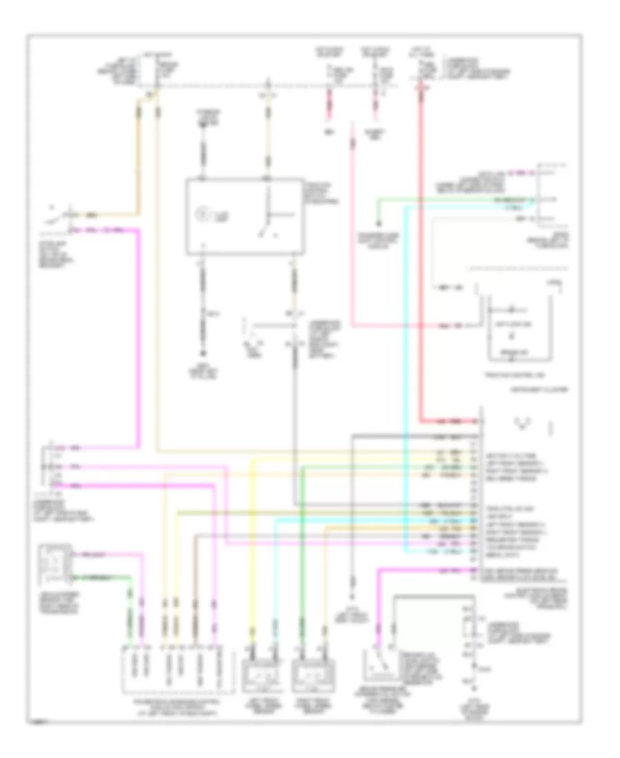
Anti-lock Brakes Wiring Diagram, with Vehicle Speed Enhancement Stability (2 of 2) for GMC Yukon XL C1500 2004
List of elements for Anti-lock Brakes Wiring Diagram, with Vehicle Speed Enhancement Stability (2 of 2) for GMC Yukon XL C1500 2004:
- (in steering column harn)
- 5v ref
- Abs ind
- Anti-theft system
- B11 c2
- B7 c2
- Battery (+)
- Body control module (on lower left side of dash, below steering column)
- Brake fluid level switch (on left side of brake fluid reservoir)
- Brake ind
- Brake pressure differential switch (below master cylinder)
- C1 c4
- C2 b7
- C3 b7
- Connector (dlc) (below steering column)
- Cruise fuse 10a
- Data link
- Electronic power steering system (rear wheel steering control module) (if equipped)
- Except 8s8
- G104 (left rear of engine block)
- G203 (near left "a" pillar)
- Ground
- Hot in run
- Hot in run or start
- Ign e fuse 10a
- Instrument panel cluster
- Interior lights system
- Left i/p fuse block (on lower left side of dash)
- Lo ref
- Logic
- Pnk
- S102
- S106
- S212 (in i/p harn)
- S213
- S216
- S240
- S241
- Seo ign fuse 10a
- Sp205 (behind left i/p fuse bock)
- Steering wheel pos marker pulse sig
- Steering wheel position sens sig
- Steering wheel position sig a
- Steering wheel position sig b
- Steering wheel speed/ position sensor (near base of steering column)
- Theft deterrent control module
- Traction control switch
- Transfer case shift control module
- Underhood fuse block (at left side of eng compt, near battery)
- W/ 8s8
- Yaw & lateral acceleration sensor (under right front seat)
- Yaw rate frequency
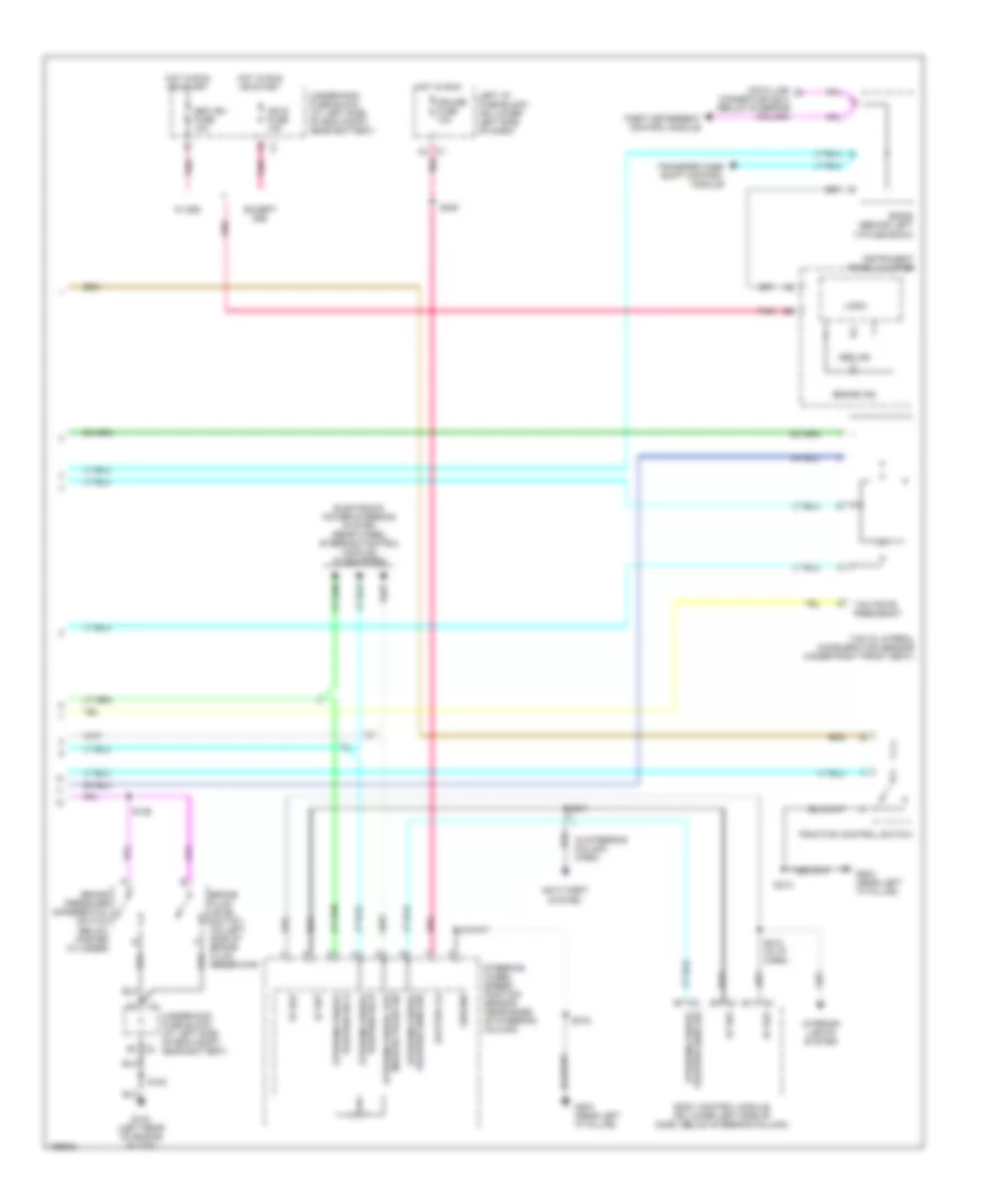
Anti-lock Brakes Wiring Diagram, without Vehicle Speed Enhancement Stability for GMC Yukon XL C1500 2004
List of elements for Anti-lock Brakes Wiring Diagram, without Vehicle Speed Enhancement Stability for GMC Yukon XL C1500 2004:
- (not used)
- 1500: brake press sens sig
- 2500: brake fluid level sw
- Abs fuse 60a
- Anti-lock ind
- Brake fluid level switch (2500 series) (on left side of brake fluid reservoir)
- Brake fuse 10a
- Brake ind
- Brake pressure differential switch (1500 series) (below master cylinder)
- C12
- C2 b7
- C5 c1
- C9 a
- Data link connector (dlc) (under left side of dash, below steering column)
- Del torque
- Delivered torque
- Electronic brake control module (ebcm) (on left rear frame rail)
- Except seo
- G104 (left rear of engine block)
- G110 (left front body mount)
- G203 (near left "a" pillar)
- Hot at all times
- Hot in run
- Hot in run or start
- Ign e fuse 10a
- Ignition 3 voltage
- Illum lamp
- Instrument cluster
- Interior lights system
- Left front sensor (+)
- Left front sensor (-)
- Left front wheel speed sensor
- Left i/p fuse block (behind lower left side of dash)
- Logic
- Nca
- Pnk
- Powertrain or engine control module (pcm or ecm) (at left front of eng compt)
- Red
- Req torque
- Requested torque
- Right front sensor (+)
- Right front sensor (-)
- Right front wheel speed sensor
- S102
- S213
- Seo
- Seo ign fuse 10a
- Serial data
- Sp205 (behind left i/p fuse block)
- Stoplamp switch (on top of brake pedal bracket)
- Tan
- Tcc brake sw
- Tcc brake switch
- Trac ctrl sw sig
- Traction control ind
- Traction control switch (if equipped)
- Transfer case shift control module
- Underhood fuse block (at left side of eng compt, near battery)
- Underhood fuse block (at left side of engine compt, near battery)
- Vehicle speed sensor (vss) (right rear of transmission)
- Vss high
- Vss input
- Vss low
- Vss out
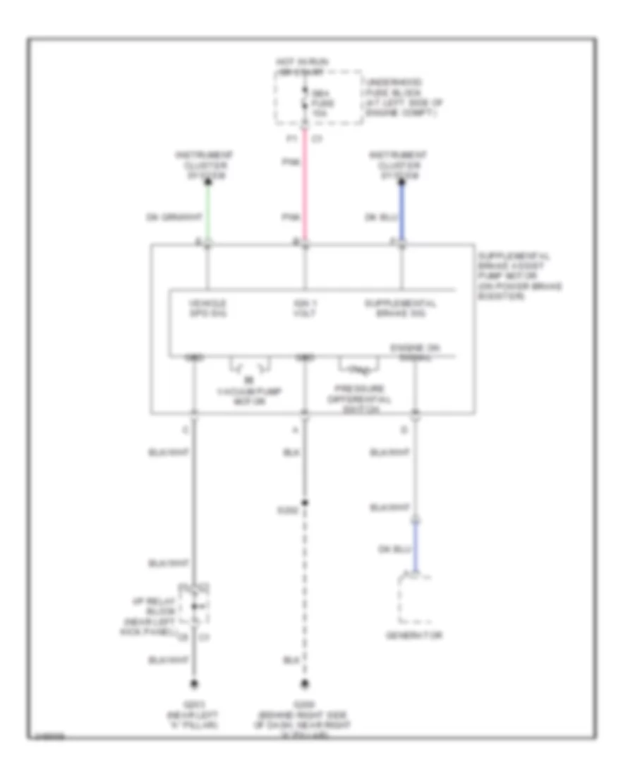
Supplemental Brake Assist Wiring Diagram for GMC Yukon XL C1500 2004
List of elements for Supplemental Brake Assist Wiring Diagram for GMC Yukon XL C1500 2004:
- C1 f5
- C5 c1
- Engine on signal
- G200 (behind right side of dash, near right "a" pillar)
- G203 (near left "a" pillar)
- Generator
- Grd
- Hot in run or start
- I/p relay block (near left kick panel)
- Ign 1 volt
- Instrument cluster system
- Pnk
- Pressure differential switch
- S202
- Sba fuse 15a
- Underhood fuse block (at left side of engine compt)
- Vacuum pump motor
- Vehicle spd sig