ANTI-LOCK BRAKES
2.4L
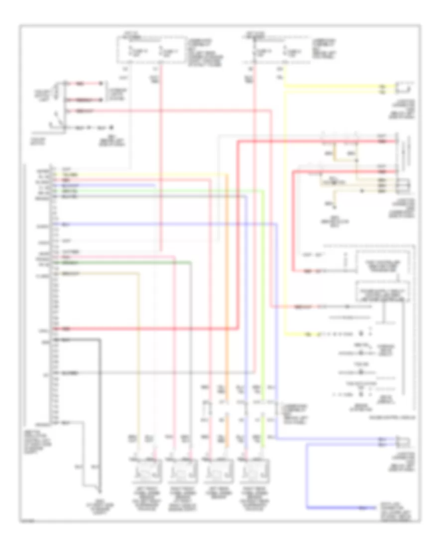
2.4L, Anti-lock Brakes Wiring Diagram for Honda Accord DX 2005

List of elements for 2.4L, Anti-lock Brakes Wiring Diagram for Honda Accord DX 2005:
- +b-fsr
- +b-mr
- Abs
- Abs ind
- Abs modulator- control unit (at right side of engine compt)
- Brake pedal position switch (on brake pedal support)
- Brake system ind
- C10
- C11
- C12
- Data link connector (on lower left of dash, above the kick panel)
- Diagk
- E12
- Ebd
- Except usa dx, lx
- Fl +b
- Fl-gnd
- Fr +b
- Fr-gnd
- Fuse 13 20a
- Fuse 17 30a
- Fuse 18 15a
- Fuse 18 20a
- Fuse 21 7.5a
- G203 (at right side of engine compt)
- Gauge control module
- Gnd
- Hot at all times
- Hot in on or start
- Ig1
- Junction connector c404 (below left side of dash)
- Junction connector c405 (below left side of dash)
- Junction connector c406 (below left side of dash)
- Left front wheel speed sensor (on left front suspension knuckle)
- Left rear wheel speed sensor
- Mr-gnd
- N13
- N14
- N21
- Pnk
- Red
- Right front wheel speed sensor (on right front suspension knuckle)
- Right rear wheel speed sensor (on right rear suspension knuckle)
- Rl +b
- Rl-gnd
- Rr +b
- Rr-gnd
- Scs
- Stop
- Under-dash fuse/relay box (behind left kick panel)
- Under-hood fuse/relay box (on left rear corner of engine compt, forward of strut tower)
- Warning drive circuit
- X28
- X34
3.0L
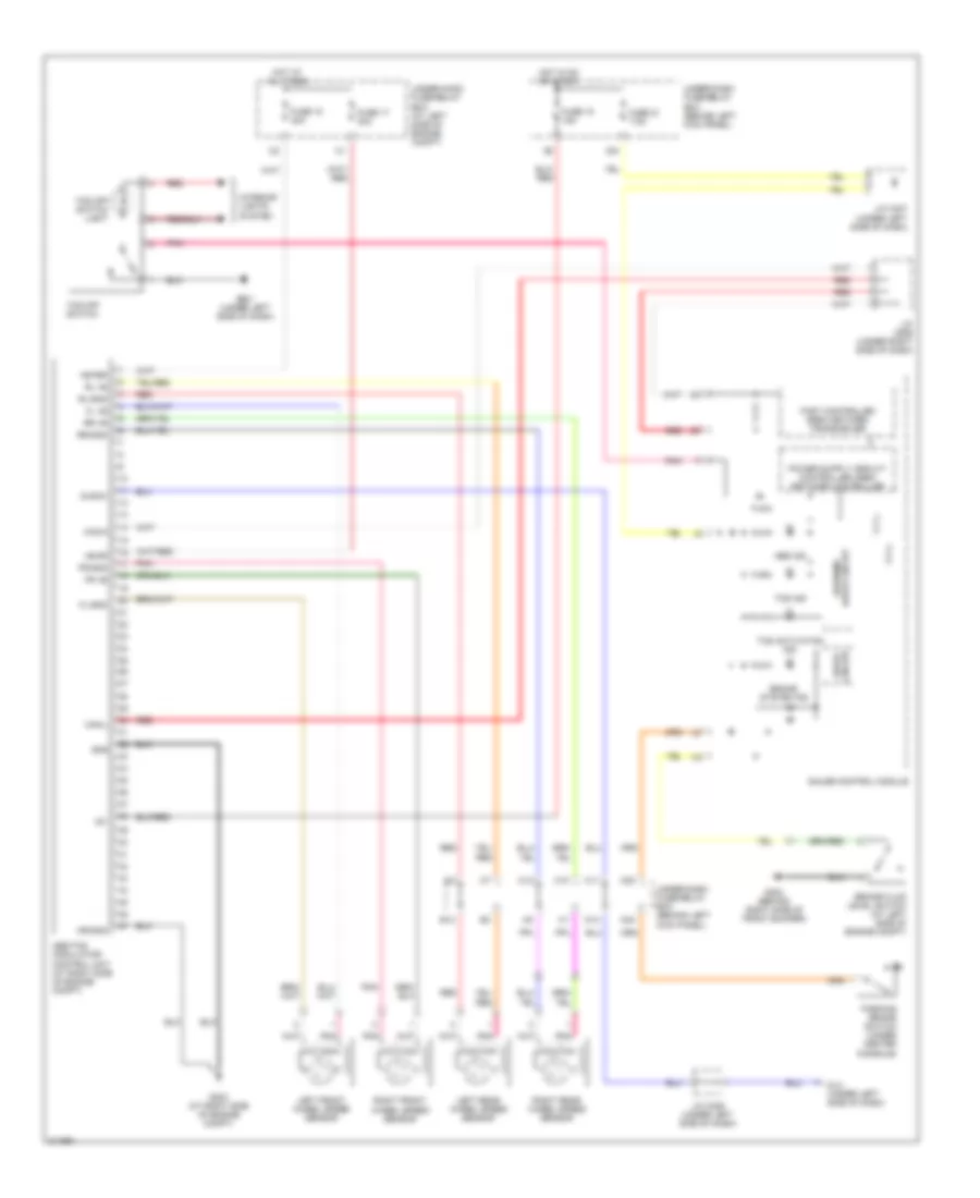
3.0L, Anti-lock Brakes Wiring Diagram, Except Hybrid for Honda Accord DX 2005
List of elements for 3.0L, Anti-lock Brakes Wiring Diagram, Except Hybrid for Honda Accord DX 2005:
- +b-fsr
- +b-mr
- Abs ind
- Abs/tcs modulator- control unit (at right side of engine compt)
- Brake system ind
- C10
- C11
- C12
- Can-h
- Can-l
- Data link connector (on lower left of dash, above the kick panel)
- Diag-k
- Drive circuit
- E12
- Ex-l: navigation
- Fast controller area network transceiver
- Fl +b
- Fl-gnd
- Fr +b
- Fr-gnd
- Fuse 17 30a
- Fuse 18 15a
- Fuse 18 40a
- Fuse 21 7.5a
- G203 (at right side of engine compt)
- G501 (behind left side of dash)
- G503 (behind glove box)
- Gauge control module
- Gnd
- Hot at all times
- Hot in on or start
- Ig1
- Interior lights system
- Junction connector c404 (below left side of dash)
- Junction connector c405 (below left side of dash)
- Junction connector c555 (under right side of dash)
- Left front wheel speed sensor (on left front suspension knuckle)
- Left rear wheel speed sensor
- Mr-gnd
- N13
- Pnk
- Red
- Right front wheel speed sensor (at right front side of engine compt)
- Right rear wheel speed sensor (on right rear suspension knuckle)
- Rl +b
- Rl-gnd
- Rr +b
- Rr-gnd
- Tcs activation ind
- Tcs ind
- Tcs off switch
- Tcs off switch light
- Under-dash fuse/relay box (behind left kick panel)
- Under-hood fuse/relay box (on left rear corner of engine compt, forward of strut tower)
- Warning drive circuit
- X34
3.0L, Anti-lock Brakes Wiring Diagram, Hybrid for Honda Accord DX 2005
List of elements for 3.0L, Anti-lock Brakes Wiring Diagram, Hybrid for Honda Accord DX 2005:
- +b-fsr
- +b-mr
- Abs ind
- Abs/tcs modulator- control unit (at right side of engine compt)
- Brake fluid level switch (at left side of engine compt)
- Brake system ind
- C10
- C11
- C12
- Can-h
- Can-l
- Circuit drive
- Diag-k
- Dlc (under left side of dash)
- E12
- Fast controller area network transceiver
- Fl +b
- Fl-gnd
- Fr +b
- Fr-gnd
- Fuse 17 30a
- Fuse 18 15a
- Fuse 18 40a
- Fuse 21 7.5a
- G202 (behind right side of front bumper)
- G203 (at right side of engine compt)
- G501 (under left side of dash)
- Gauge control module
- Gnd
- Hot at all times
- Hot in on or start
- Ig1
- Interior lights system
- J/c c406 (under left side of dash)
- J/c c407 (under left side of dash)
- J/c c555 (under right side of dash)
- Left front wheel speed sensor
- Left rear wheel speed sensor
- Mr-gnd
- N13
- N30
- N34
- Parking brake switch (under center console)
- Pnk
- Red
- Right front wheel speed sensor
- Right rear wheel speed sensor
- Rl +b
- Rl-gnd
- Rr +b
- Rr-gnd
- Tcs activation ind
- Tcs ind
- Tcs off switch
- Tcs off switch light
- Under-dash fuse/relay box (behind left kick panel)
- Under-hood fuse/relay box (at left side of engine compt)
- Warning drive circuit
- X34