ANTI-LOCK BRAKES
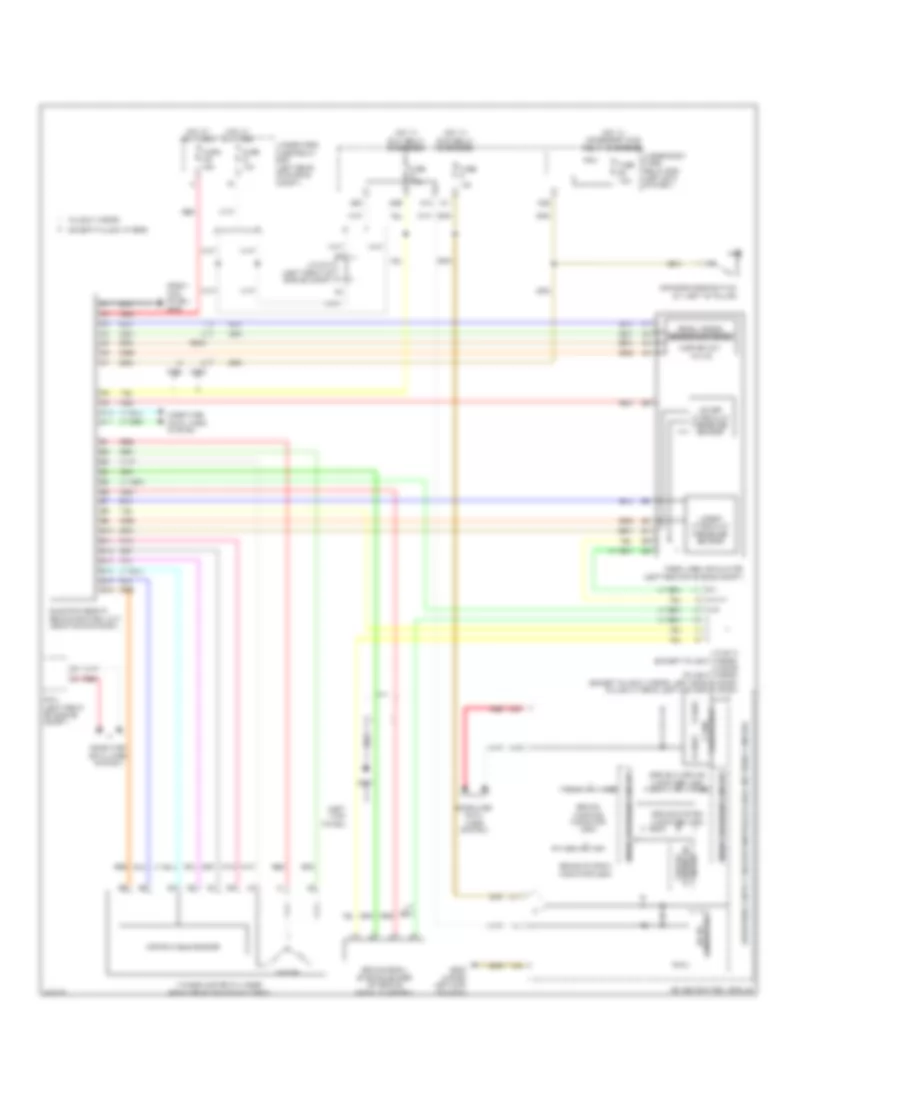
Anti-Lock Brakes Wiring Diagram, Except Hybrid for Honda Accord Plug-In 2014

List of elements for Anti-Lock Brakes Wiring Diagram, Except Hybrid for Honda Accord Plug-In 2014:
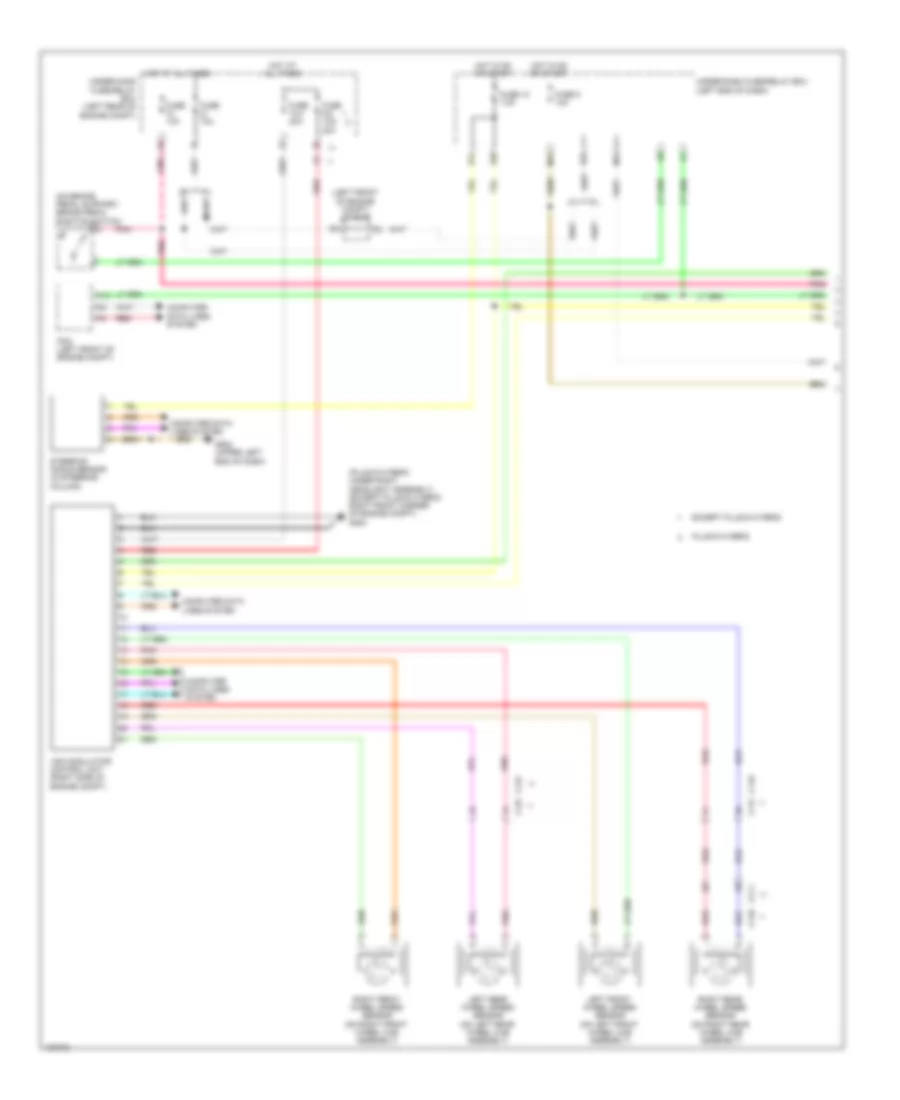
Anti-Lock Brakes Wiring Diagram, Hybrid (1 of 2) for Honda Accord Plug-In 2014
List of elements for Anti-Lock Brakes Wiring Diagram, Hybrid (1 of 2) for Honda Accord Plug-In 2014:
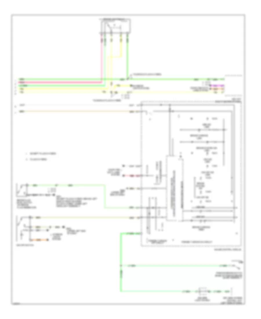
Anti-Lock Brakes Wiring Diagram, Hybrid (2 of 2) for Honda Accord Plug-In 2014
List of elements for Anti-Lock Brakes Wiring Diagram, Hybrid (2 of 2) for Honda Accord Plug-In 2014:
Electric Servo Brake System Wiring Diagram, Hybrid for Honda Accord Plug-In 2014
List of elements for Electric Servo Brake System Wiring Diagram, Hybrid for Honda Accord Plug-In 2014: