ANTI-LOCK BRAKES
Advanced Hydraulic Booster Wiring Diagram for Honda Civic Natural Gas 2013

List of elements for Advanced Hydraulic Booster Wiring Diagram for Honda Civic Natural Gas 2013:
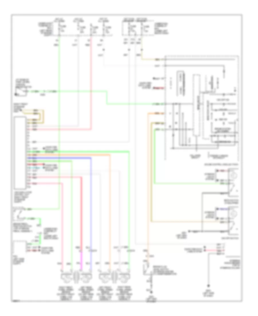
Anti-Lock Brakes Wiring Diagram, Except Hybrid for Honda Civic Natural Gas 2013
List of elements for Anti-Lock Brakes Wiring Diagram, Except Hybrid for Honda Civic Natural Gas 2013:
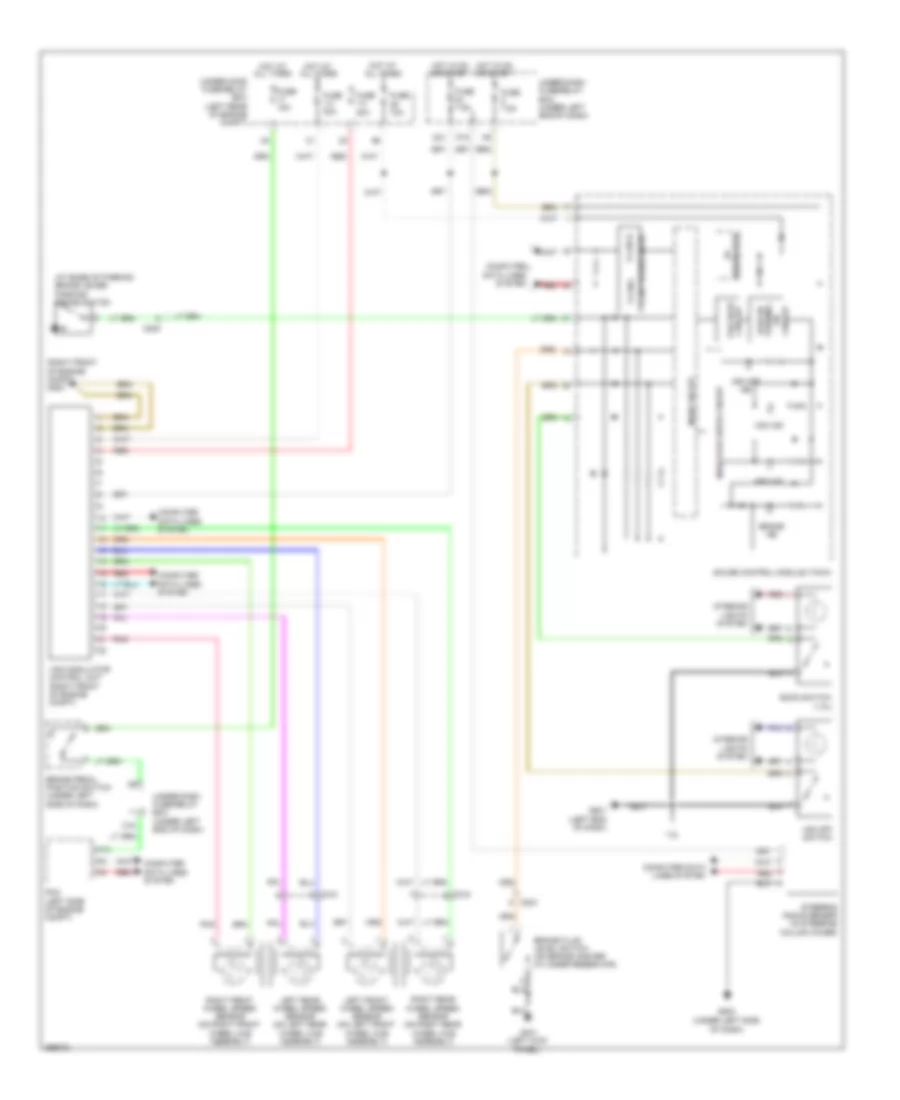
Anti-Lock Brakes Wiring Diagram, Hybrid for Honda Civic Natural Gas 2013
List of elements for Anti-Lock Brakes Wiring Diagram, Hybrid for Honda Civic Natural Gas 2013: