ANTI-LOCK BRAKES
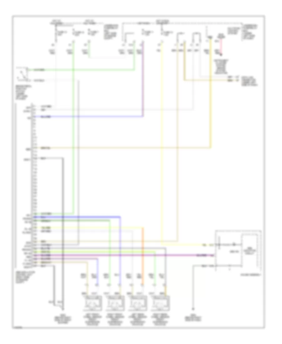
Anti-lock Brakes Wiring Diagram for Honda Element LX 2004
List of elements for Anti-lock Brakes Wiring Diagram for Honda Element LX 2004:
- +b-p
- +b-v
- A14
- A15
- Abs
- Abs ind
- Abs indicator circuit
- Abs modulator control unit (right side of engine compt)
- B10
- Brake pedal position switch (under left side 0f dash)
- Bus meter
- Data link connector (under left side of dash)
- Diag-ii
- Ebd
- Fl +b
- Fl-gnd
- Fr +b
- Fr-gnd
- Fuse 10 30a
- Fuse 10 7.5a
- Fuse 11 7.5a
- Fuse 18 30a
- Fuse 7 15a
- G202 (behind right side of front bumper)
- G502 (behind right side of dash)
- Gauge assembly
- Gnd-p
- Gnd-v
- Hot at all times
- Hot in on
- Hot in run or start
- Ig2
- Instrument cluster system (brake system indicator)
- Left front wheel sensor (front suspension knuckle)
- Left rear wheel sensor (front suspension knuckle)
- Multiplex control system
- O12
- Right front wheel sensor (front suspension knuckle)
- Right rear wheel sensor (front suspension knuckle)
- Rl +b
- Rl-gnd
- Rr +b
- Rr-gnd
- Scs
- Stop
- Underdash fuse/relay box (under left side of dash)
- Underhood fuse/relay box (left side of engine compt)
 English