ANTI-LOCK BRAKES
Anti-lock Brakes Wiring Diagram for Honda Element LX 2008
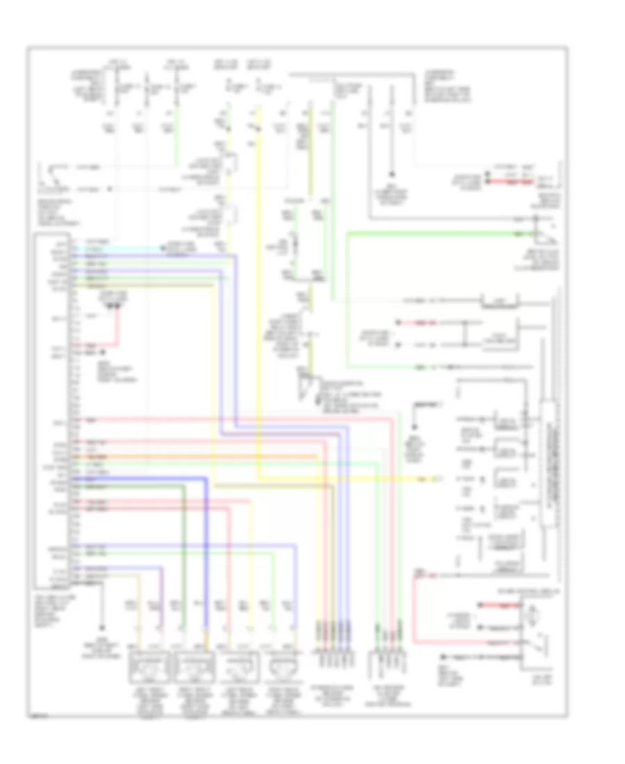
List of elements for Anti-lock Brakes Wiring Diagram for Honda Element LX 2008:
- +b p
- +b v
- 5v stabilize circuit/controller area network controller
- Abs ind
- Brake fluid level switch (on brake fluid reservoir)
- Brake pedal position switch (on brake pedal support)
- Brake system ind
- Can h
- Can l
- Canada
- Clst gnd
- Clst ig
- Compulsory turning-on circuit
- Computer data lines system
- Diag ii
- Drive circuit
- Drl control unit
- E11
- E22
- E24
- Ecm/pcm (behind glove box)
- F-can tranceiver
- Fail-safe circuit
- Fl b+
- Fl gnd
- Fr b+
- Fr gnd
- Fuse 10 30a
- Fuse 10 7.5a
- Fuse 18 30a
- Fuse 4 10a
- Fuse 7 15a
- G202 (behind right side of front bumper)
- G401 (under right middle side of dash)
- G501 (behind left side of dash)
- G502 (behind right side of dash)
- Gauge control module
- Gnd p
- Gnd v
- Hot at all times
- Hot in on or start
- Ig2
- Interior lights system
- Junction connector c405 (under middle of dash)
- Junction connector c457 (under middle of dash)
- K10
- Left front wheel speed sensor (left side of engine compt)
- Left rear wheel speed sensor (on left rear wheel)
- Multiplex control unit
- Parking brake switch (ex, lx: under center console) (sc: base of parking brake lever)
- Red
- Right front wheel speed sensor (right side of engine compt)
- Right rear wheel speed sensor (on right rear wheel)
- Rl b+
- Rl gnd
- Rr b+
- Rr gnd
- S gnd
- Steering angle sensor (on steering column)
- Stra
- Strb
- Strz
- Svcc
- Uart tranceiver
- Under- dash fuse/ relay box (behind left side of dash, right of steering column)
- Underdash fuse/relay box (behind left side of dash, right of steering column)
- Underhood fuse/relay box (left rear of engine compt)
- Usa
- Vsa activation ind
- Vsa ind
- Vsa modulator- control unit (right rear corner of engine compt)
- Vsa off switch
- Vsa sensor cluster (under center console)
- Warning drive circuit
 English