ANTI-LOCK BRAKES
Anti-lock Brakes Wiring Diagram for Honda Pilot LX 2005
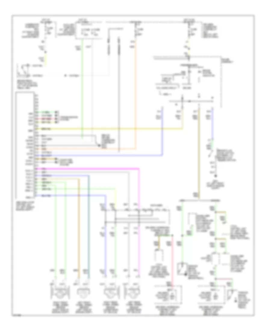
List of elements for Anti-lock Brakes Wiring Diagram for Honda Pilot LX 2005:
- (below driver underdash fuse/relay box) g302
- (not used)
- +b-fsr
- +b-mr
- Abs
- Abs indicator
- Abs modulator control unit (at left side of engine compt)
- Auxiliary fuse box (at left side of engine compartment)
- B15
- B17
- B18
- B19
- Brake fluid level switch (integral to brake fluid reservoir cap)
- Brake pedal position switch (at top of brake pedal arm)
- Brake system indicator
- C14
- Canada
- Computer data lines system
- Cpu
- D15
- D16
- Diag-k
- Diag-l
- Driver
- Driver's multiplex control unit
- Driver's underdash fuse/relay box (below left end of dash)
- Drl control unit
- Ebd
- F13
- F14
- Fail safe circuit
- Flp
- Fls (+)
- Fls (-)
- Frp
- Frs (+)
- Frs (-)
- Fuse 10a
- Fuse 20a
- Fuse 40a
- Fuse 7.5a
- G301 (at left front side of engine compt)
- Gauge assembly
- Gnd
- Hot at all times
- Hot in on
- Hot in on or start
- Ig2
- Immobilizer control unit-receiver (in steering column, on ignition key cylinder)
- Immobilizer control unit-receiver (in steering column, on ignition key cylinder
- J17
- Left front wheel speed sensor (left side of engine compt)
- Left rear wheel speed sensor (under rear of vehicle)
- M-gnd
- M10
- M20
- P/ brk sw
- Parking brake switch (at top of parking brake pedal)
- Power block
- Right front wheel speed sensor (right side of engine compt)
- Right rear wheel speed sensor (under rear of vehicle)
- Rlp
- Rls (+)
- Rls (-)
- Rrp
- Rrs (+)
- Rrs (-)
- Stop
- Transmissions system
- Turn on circuit
- Underhood fuse/relay box (at right side of engine compartment)
- Usa
- Vtm-4 control unit (at left side of cargo area, behind rear side trim panel)
 English