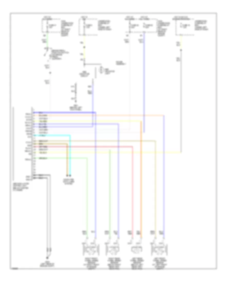
ANTI-LOCK BRAKES
Anti-lock Brakes Wiring Diagram for Honda S2000 2005
List of elements for Anti-lock Brakes Wiring Diagram for Honda S2000 2005:
- A18
- Abs indicator circuit
- Abs indicator light
- Abs modulator/ control unit (below master cylinder)
- B20
- Brake pedal position switch (on brake pedal support)
- Computer data lines system
- Dlc
- Flw(+)
- Flw(-)
- Frw(+)
- Frw(-)
- Fsr+b
- Fuse 19 7.5a
- Fuse 47 15a
- Fuse 48 20a
- Fuse 5 7.5a
- Fuse 50 30a
- G303 (left rear of engine compt)
- G501 (behind left kick panel)
- Gauge assembly
- Gnd 1
- Gnd 2
- Hot at all times
- Hot in on
- Hot in on w/o engine cranking
- Ig2
- Left front wheel speed sensor (at left front of engine compt)
- Left rear wheel speed sensor (below left rear tray rear trim)
- Main under-hood fuse/relay box (at right rear of engine compt)
- Mr+b
- Right front wheel speed sensor (at right front of engine compt)
- Right rear wheel speed sensor (below right rear tray rear trim)
- Rlw(+)
- Rlw(-)
- Rrw(+)
- Rrw(-)
- Scs
- Stop
- Under-dash fuse/relay box (under left side of dash)
- Walp
 English