ANTI-LOCK BRAKES
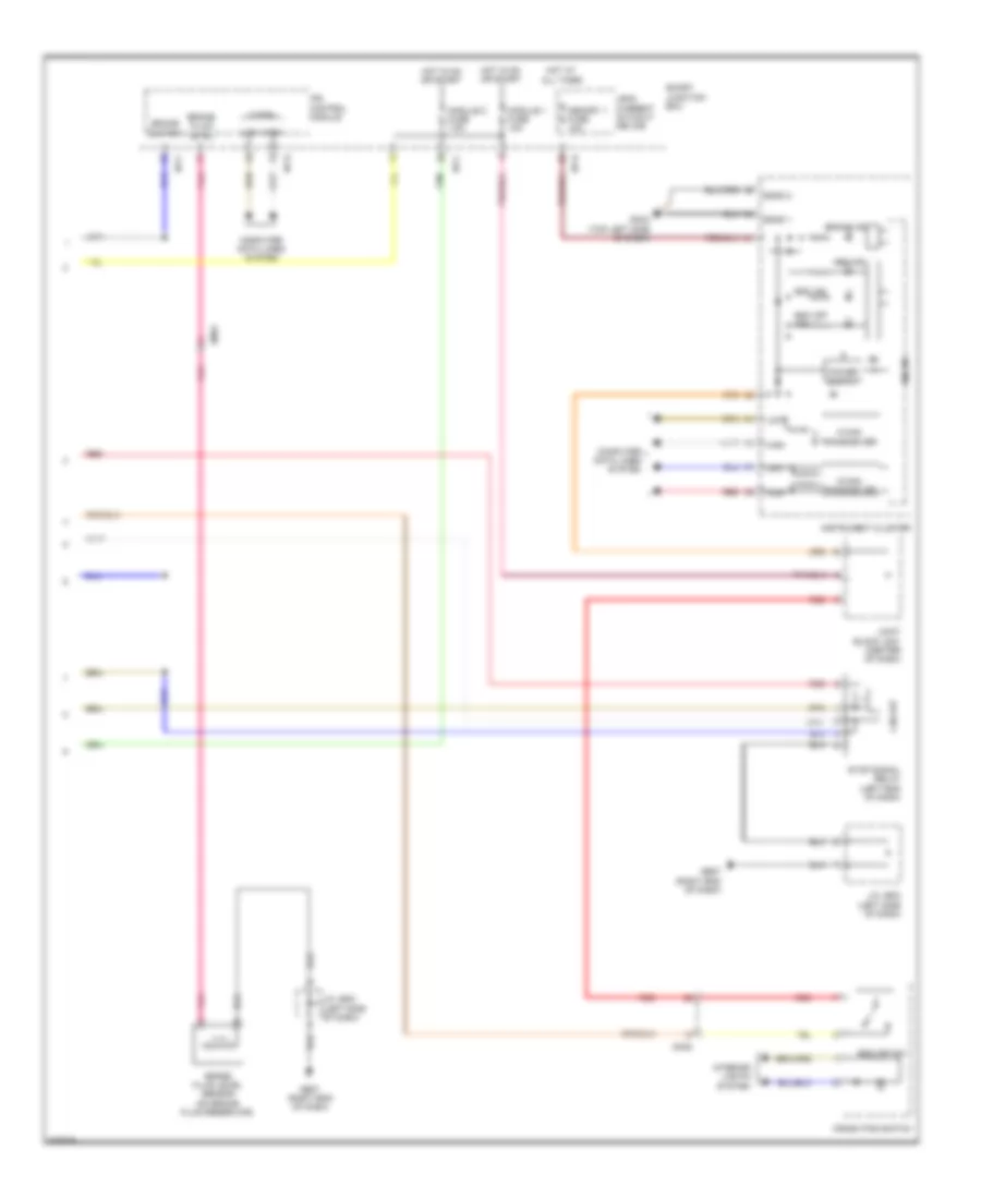
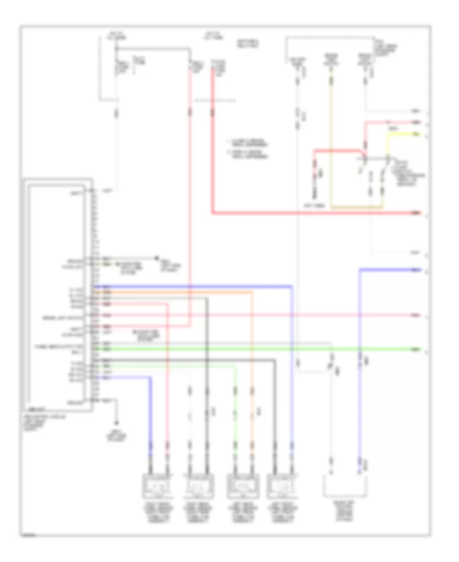
Anti-lock Brakes Wiring Diagram, with ESC (1 of 2) for Hyundai Azera 2013

List of elements for Anti-lock Brakes Wiring Diagram, with ESC (1 of 2) for Hyundai Azera 2013:
- (not used)
- Brake light switch
- Brake test switch
- C-can high
- C-can low
- Can high
- Can low
- Clg-b
- Close w/ brake pedal depressed
- Computer data lines system
- E/r fuse & relay box
- Ec21
- Ecu +
- Ef01
- Ef21
- Elg-a
- Em21
- Em31
- Esc 1 fuse 40a
- Esc 2 fuse 40a
- Esc control module (left rear of engine compt)
- Esc on/off switch
- Esc unit
- Exterior lights system
- Fl sig
- Fl vcc
- Fr sig
- Fr vcc
- Front parking brake switch
- Ge10 (left side of dash)
- Gnd
- Ground
- Hot at all times
- Left front wheel sensor (left front wheel hub assembly)
- Left rear wheel sensor (left rear wheel hub assembly)
- M13-b
- Multi fuse
- Nca
- Open w/ brake pedal depressed
- Parking brake sw
- Pcm (left rear of engine compt)
- Pnk
- Power
- Red
- Right front wheel sensor (right front wheel hub assembly)
- Right rear wheel sensor (right rear wheel hub assembly)
- Rl sig
- Rl vcc
- Rr sig
- Rr vcc
- Rsm
- Smart key control module (center of dash)
- Stop lamp fuse 15a
- Stop lamp relay
- Stop lamp relay ctrl
- Stop lamp switch (above brake pedal, on bracket)
- Valve block
- Vbatt motor relay
- Wheel sens out (fr)
- Yaw rate sensor (front of center console)
Anti-lock Brakes Wiring Diagram, with ESC (2 of 2) for Hyundai Azera 2013
List of elements for Anti-lock Brakes Wiring Diagram, with ESC (2 of 2) for Hyundai Azera 2013:
- Abs ind
- Brake fluid level
- Brake fluid level sensor (on brake fluid reservoir)
- Brake ind
- Brake switch
- C-can
- C-can transceiver
- Circuit
- Computer data lines system
- Crash pad switch
- Em31
- Esc ind
- Esc off ind
- Esc off sw
- Ge07 (right end of dash)
- Gm04 (top left side of dash)
- High
- Hot at all times
- Hot in on or start
- I/p-c
- I/p-d
- I/p-e
- Instrument cluster
- Interior lights system
- Ips control module
- J/c je03 (left side of dash)
- Joint block jm01 (center of dash)
- Leak current autocut device
- Low
- M-can transceiver
- Memory 1 fuse 10a
- Micom
- Mm02
- Module 1 fuse 10a
- Module 2 fuse 7.5a
- Pnk
- Red
- Sgnd 1
- Sgnd 2
- Smart junction box
- Stop signal relay (left end of dash)
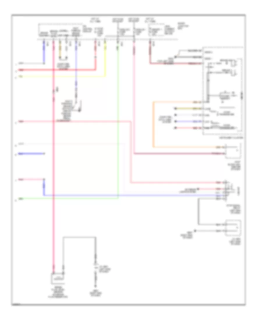
Anti-lock Brakes Wiring Diagram, without ESC (1 of 2) for Hyundai Azera 2013
List of elements for Anti-lock Brakes Wiring Diagram, without ESC (1 of 2) for Hyundai Azera 2013:
- (not used)
- Abs control module (left rear of engine compt)
- Abs unit
- Brake light switch
- Brake test switch
- C-can high
- C-can low
- Clg-b
- Close w/ brake
- Computer data lines system
- E/r fuse & relay box
- Ec21
- Ecu +
- Ef01
- Ef21
- Elg-a
- Em31
- Esc 1 fuse 40a
- Esc 2 fuse 40a
- Fl sig
- Fl vcc
- Fr sig
- Fr vcc
- Ge10 (left side of dash)
- Ground
- Hot at all times
- Left front wheel sensor (left front wheel hub assembly)
- Left rear wheel sensor (left rear wheel hub assembly)
- M13-b
- Multi fuse
- Nca
- Open w/ brake pedal depressed
- Pcm (left rear of engine compt)
- Pedal depressed
- Pnk
- Red
- Right front wheel sensor (right front wheel hub assembly)
- Right rear wheel sensor (right rear wheel hub assembly)
- Rl sig
- Rl vcc
- Rr sig
- Rr vcc
- Smart key control module (center of dash)
- Stop lamp fuse 15a
- Stop lamp switch (above brake pedal, on bracket)
- Vbatt
- Veh spd snsr
- Wheel sens output (fr)
Anti-lock Brakes Wiring Diagram, without ESC (2 of 2) for Hyundai Azera 2013
List of elements for Anti-lock Brakes Wiring Diagram, without ESC (2 of 2) for Hyundai Azera 2013:
- Abs ind
- Brake fluid level
- Brake fluid level sensor (on brake fluid reservoir)
- Brake ind
- Brake switch
- C-can
- C-can transceiver
- Circuit
- Computer data lines system
- Em31
- Exterior lights system
- Foot parking brake switch
- Foot parking brake switch (above parking brake pedal, on bracket)
- Ge07 (right end of dash)
- Gm04 (top left side of dash)
- High
- Hot at all times
- Hot in on or start
- I/p-c
- I/p-d
- I/p-e
- Instrument cluster
- Ips control module
- J/c je03 (left side of dash)
- Joint block jm01 (center of dash)
- Leak current autocut device
- Low
- M-can transceiver
- Memory 1 fuse 10a
- Micom
- Module 1 fuse 10a
- Module 2 fuse 7.5a
- Nca
- Pnk
- Red
- Sgnd 1
- Sgnd 2
- Smart junction box
- Stop lamp fuse 10a
- Stop signal relay (left end of dash)