ANTI-LOCK BRAKES
Anti-lock Brakes Wiring Diagram, with ESP for Hyundai Azera Limited 2007

List of elements for Anti-lock Brakes Wiring Diagram, with ESP for Hyundai Azera Limited 2007:
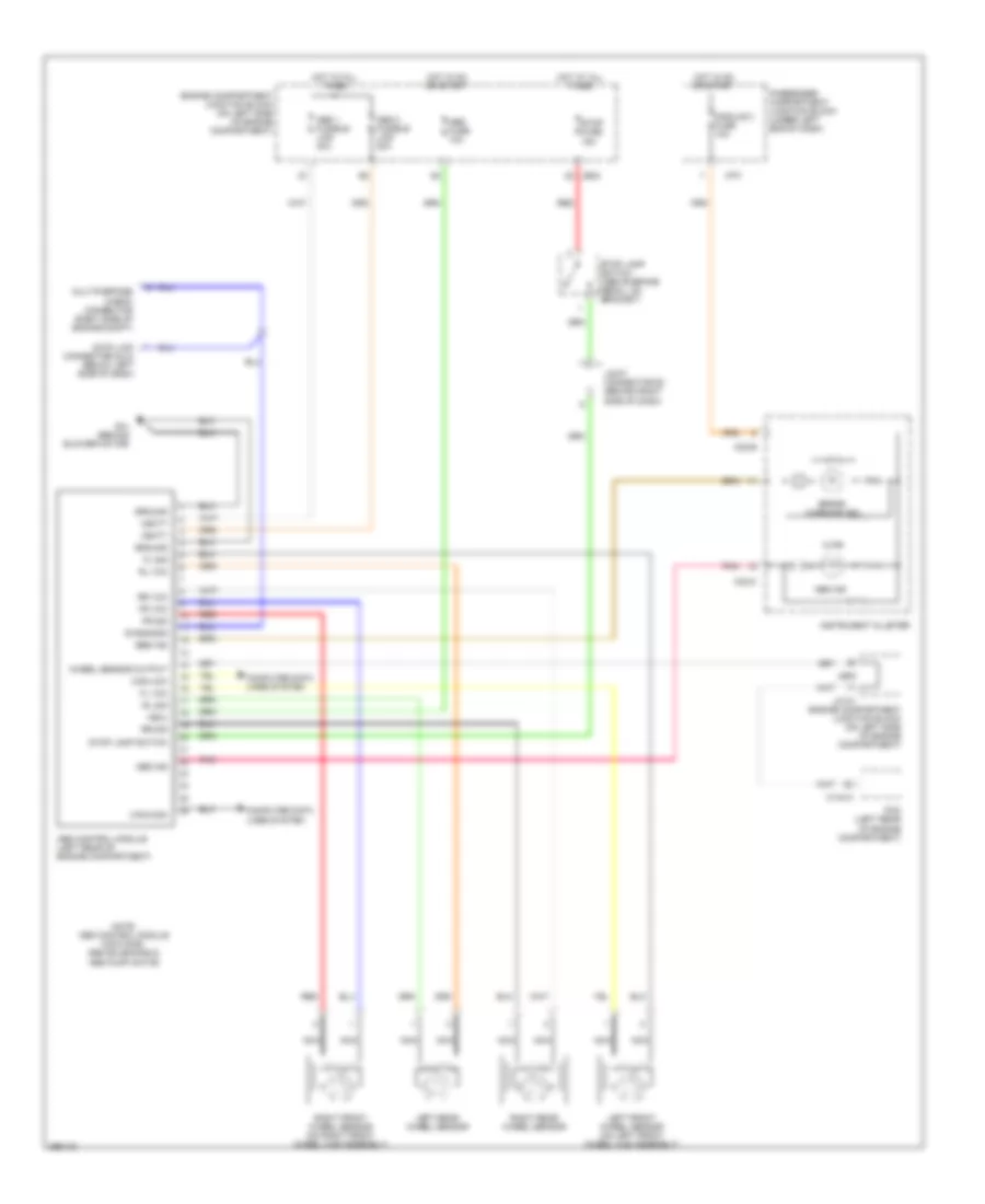
Anti-lock Brakes Wiring Diagram, without ESP for Hyundai Azera Limited 2007
List of elements for Anti-lock Brakes Wiring Diagram, without ESP for Hyundai Azera Limited 2007: