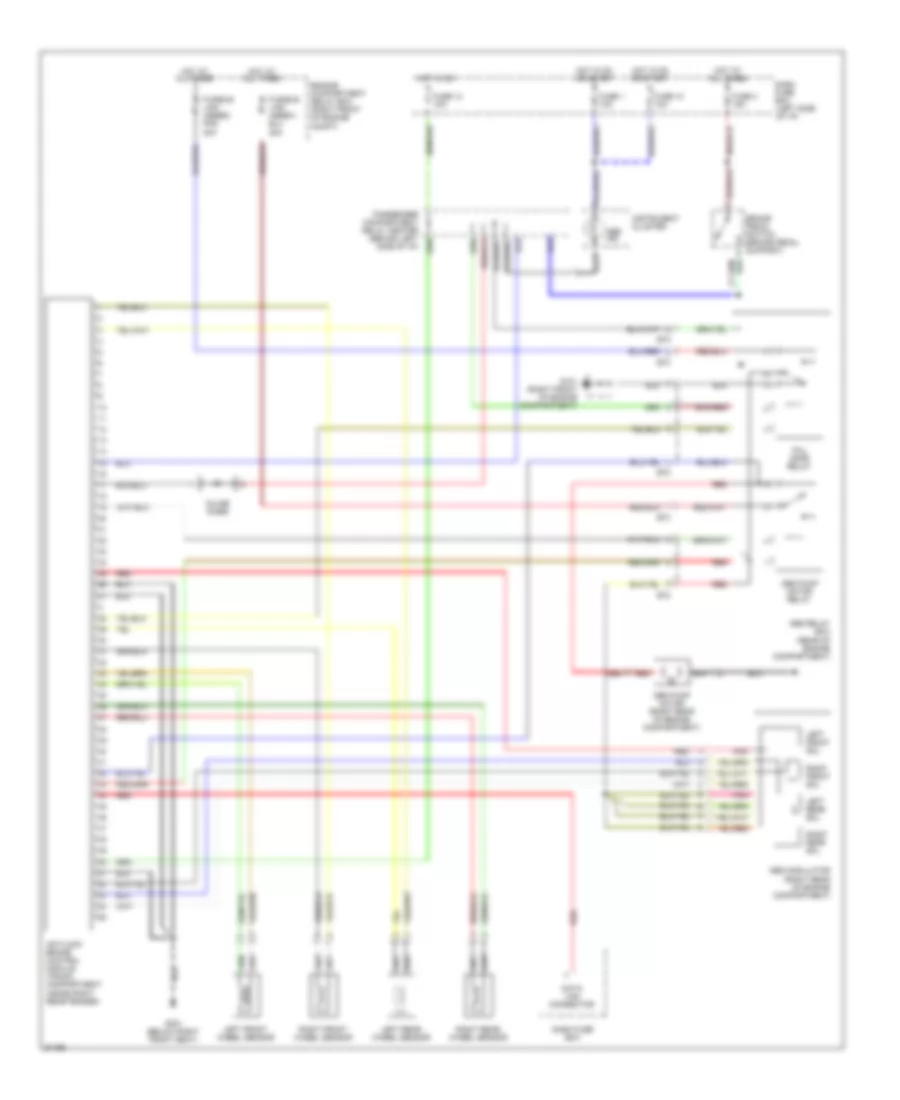
ANTI-LOCK BRAKES
Anti-lock Brake Wiring Diagrams for Hyundai Elantra 1995
List of elements for Anti-lock Brake Wiring Diagrams for Hyundai Elantra 1995:
- Abs ind
- Abs modulator (right rear of engine compartment)
- Abs pump motor (right rear of engine compartment)
- Abs pump motor relay
- Abs relay box (rear of engine compartment)
- Antilock brake control module (trunk compartment, inside right rear fender)
- Brake pedal switch (brake pedal support)
- Dash fuse box
- Dash fuse box (left side of i/p)
- Data link connector
- E72
- E73
- Engine compartment relay box (right front of engine compt)
- Fail safe relay
- Fuse 1 10a
- Fuse 10 10a
- Fuse 13 10a
- Fuse 3 15a
- Fusible link (abs#2) pnk 30a
- G101 (right front of engine compartment)
- G301 (below right front seat)
- Hot at all times
- Hot in on
- Hot in on or start
- Inline diode
- Instrument cluster
- Left front sol
- Left front wheel sensor
- Left rear sol
- Left rear wheel sensor
- Passenger compartment relay center (behind left side of i/p)
- Pnk
- Red
- Right front sol
- Right front wheel sensor
- Right rear sol
- Right rear wheel sensor
 English