ANTI-LOCK BRAKES
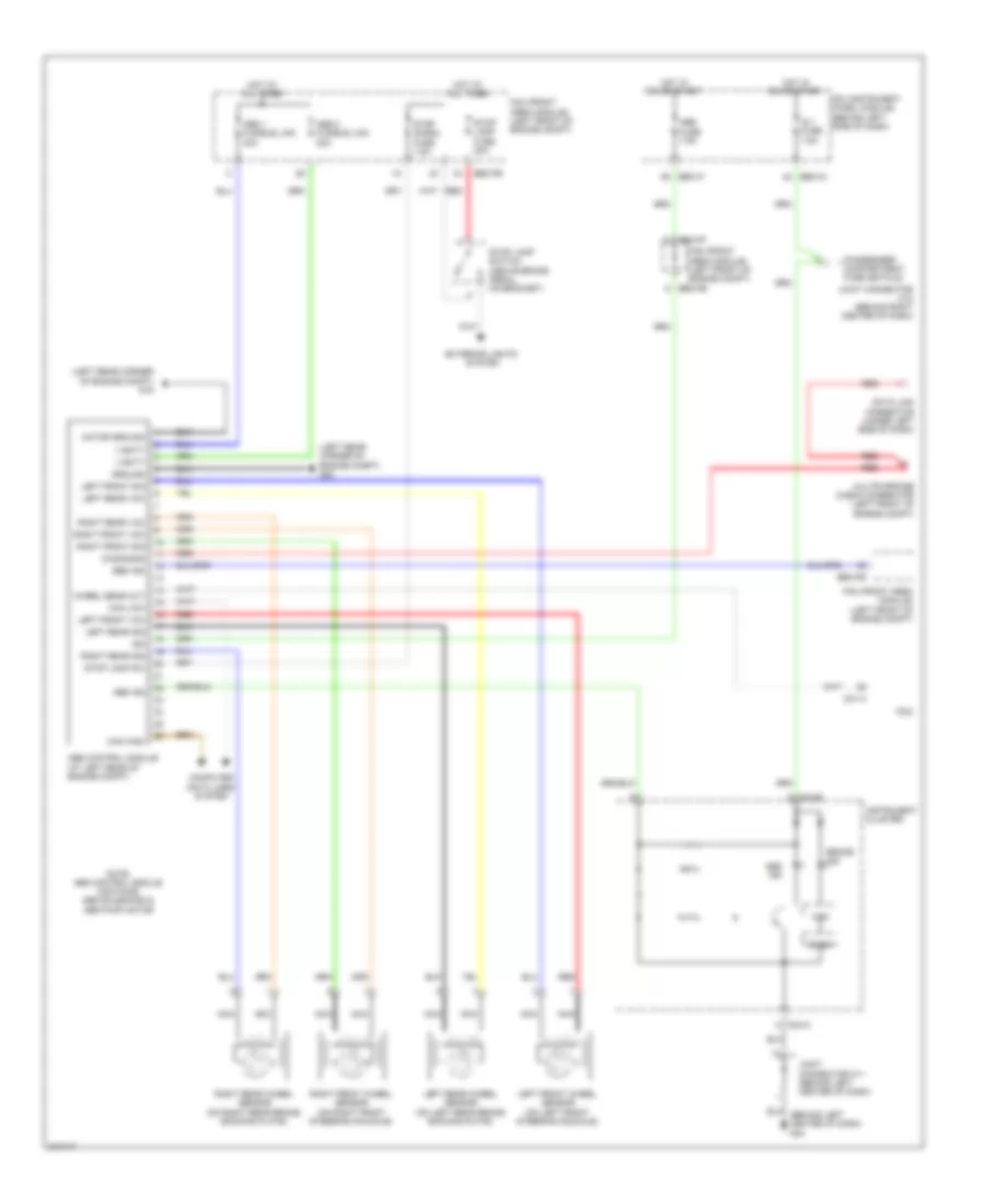
Anti-lock Brakes Wiring Diagram, with ESC (1 of 2) for Hyundai Entourage Limited 2009

List of elements for Anti-lock Brakes Wiring Diagram, with ESC (1 of 2) for Hyundai Entourage Limited 2009:
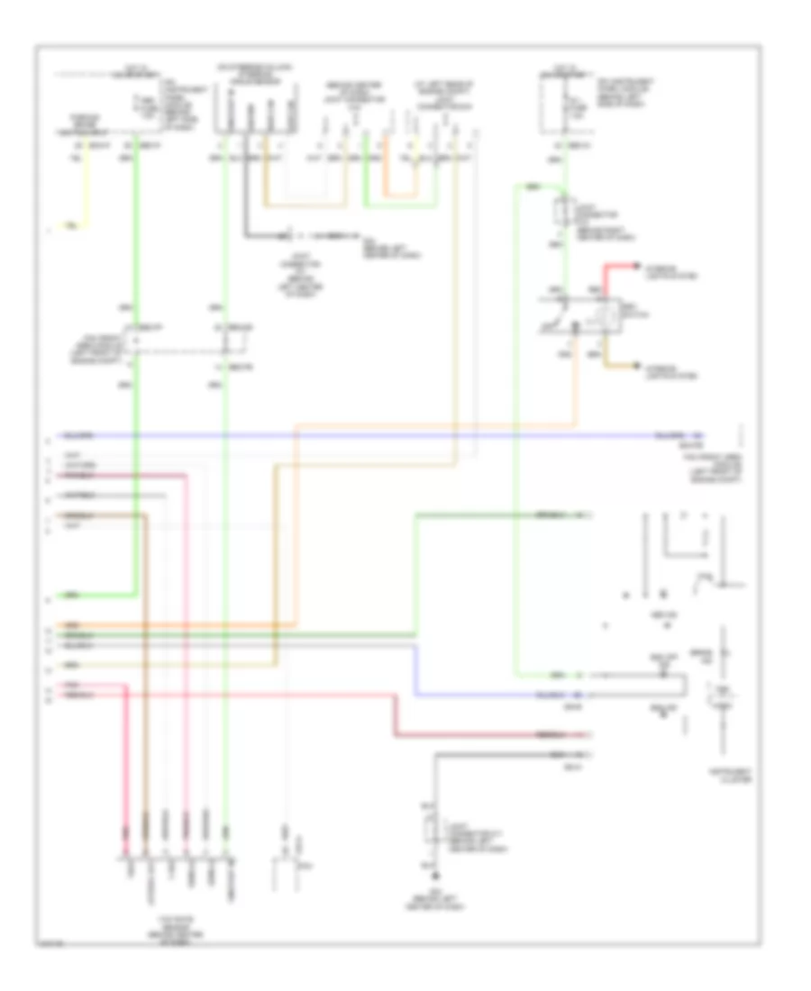
Anti-lock Brakes Wiring Diagram, with ESC (2 of 2) for Hyundai Entourage Limited 2009
List of elements for Anti-lock Brakes Wiring Diagram, with ESC (2 of 2) for Hyundai Entourage Limited 2009:
Anti-lock Brakes Wiring Diagram, without ESC for Hyundai Entourage Limited 2009
List of elements for Anti-lock Brakes Wiring Diagram, without ESC for Hyundai Entourage Limited 2009: