ANTI-LOCK BRAKES
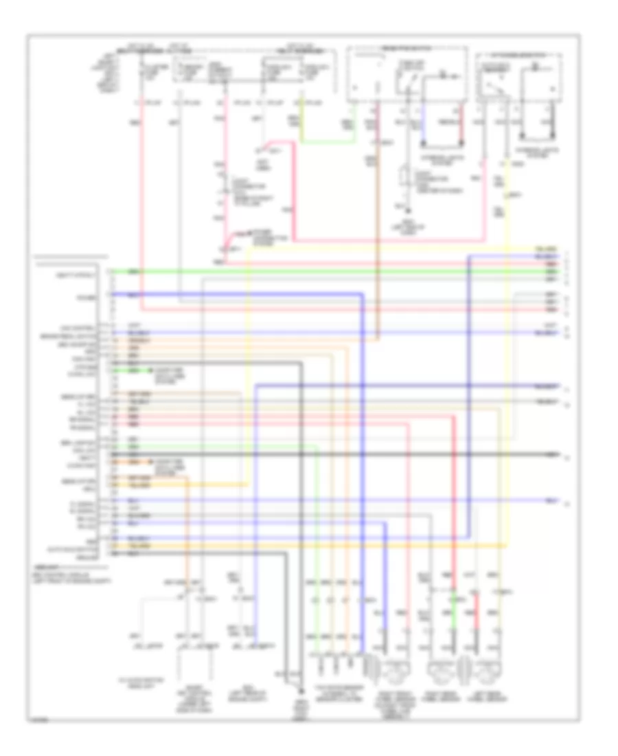
Anti-lock Brakes Wiring Diagram, Premium (1 of 2) for Hyundai Equus Signature 2014

List of elements for Anti-lock Brakes Wiring Diagram, Premium (1 of 2) for Hyundai Equus Signature 2014:
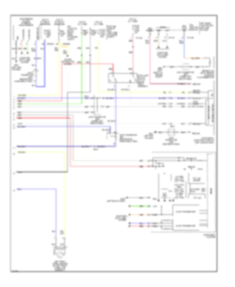
Anti-lock Brakes Wiring Diagram, Premium (2 of 2) for Hyundai Equus Signature 2014
List of elements for Anti-lock Brakes Wiring Diagram, Premium (2 of 2) for Hyundai Equus Signature 2014:
Anti-lock Brakes Wiring Diagram, Standard (1 of 2) for Hyundai Equus Signature 2014
List of elements for Anti-lock Brakes Wiring Diagram, Standard (1 of 2) for Hyundai Equus Signature 2014:
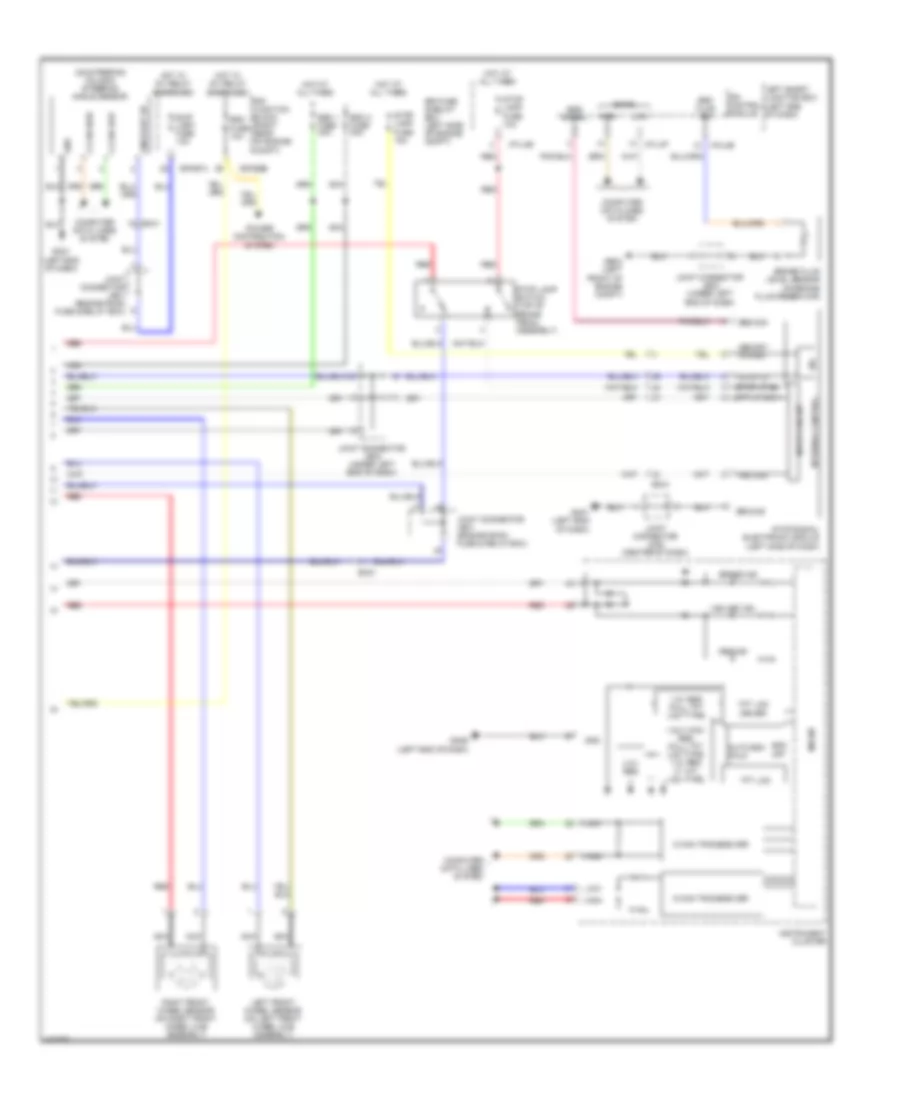
Anti-lock Brakes Wiring Diagram, Standard (2 of 2) for Hyundai Equus Signature 2014
List of elements for Anti-lock Brakes Wiring Diagram, Standard (2 of 2) for Hyundai Equus Signature 2014: