ANTI-LOCK BRAKES
Anti-lock Brake Wiring Diagrams for Hyundai Tiburon 2001
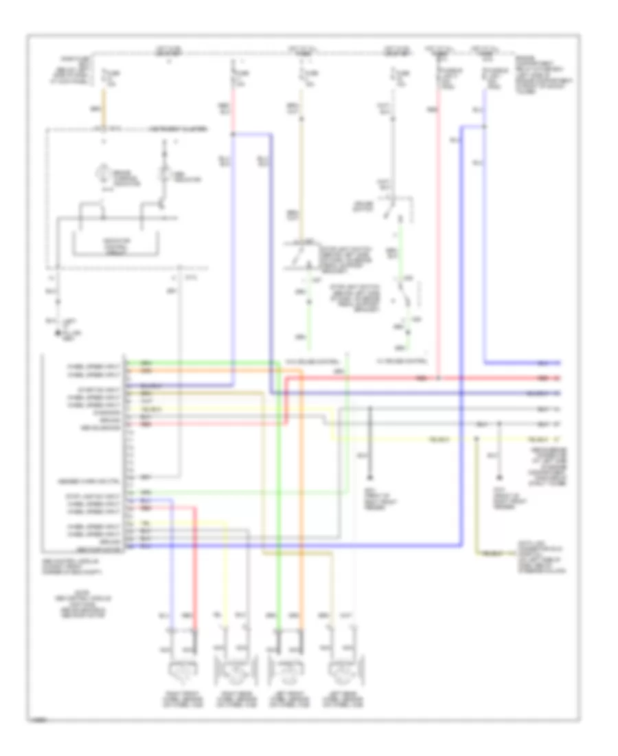
List of elements for Anti-lock Brake Wiring Diagrams for Hyundai Tiburon 2001:
- (front of right front fender)
- (left "c" pillar) g904
- Abs bleeding connector (at left side of engine compartment, forward of strut tower)
- Abs control module (in right front corner of eng compt)
- Abs indicator
- Abs pump motor
- Abs solenoids
- Abs/ebd warn ind ctrl
- Brake warning indicator
- Cruise switch
- Dash fuse box (below left side of dash, at kick panel)
- Data link connector (dlc) (partial) (on left side of dash, below steering column)
- Diagnosis
- Engine compartment relay & fuse box (left side of engine compartment, in front of shock tower)
- Fuse 10a
- Fuse 15a
- Fusible link h 30a (pnk)
- Fusible link i 30a (pnk)
- G101
- Ground
- Hot at all times
- Hot in on or start
- I01-2
- Indicator control circuit
- Instrument cluster
- Left front wheel sensor (on wheel hub)
- Left rear wheel sensor (on wheel hub)
- M27
- M28
- Nca
- Note: abs control module contains: abs solenoids & abs pump motor
- Red
- Right front wheel sensor (on wheel hub)
- Right rear wheel sensor (on wheel hub)
- Start/on input
- Stop lamp sw input
- Stoplight switch (behind left side of dash, on brake pedal support bracket)
- W/ cruise control
- W/o cruise control
- Wheel speed input
 English