ANTI-LOCK BRAKES
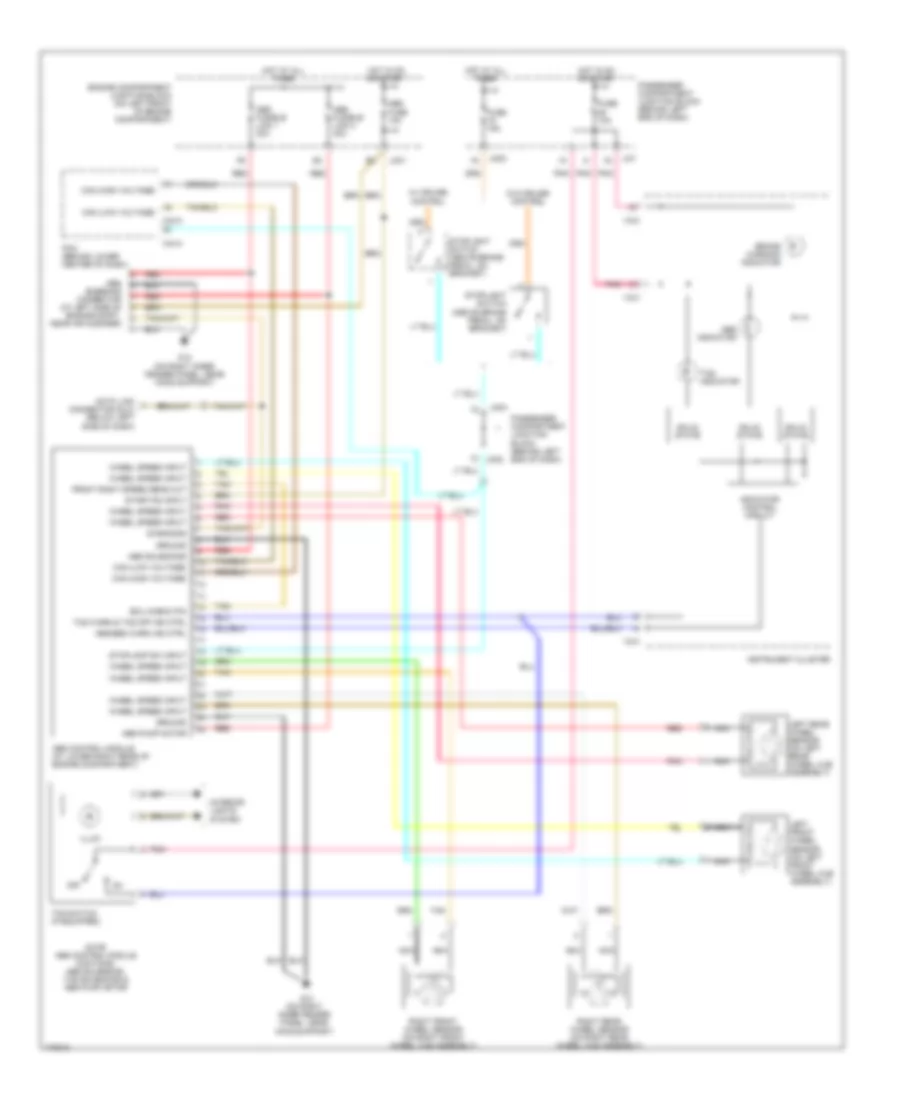
Anti-lock Brakes Wiring Diagram for Hyundai XG350 L 2003
List of elements for Anti-lock Brakes Wiring Diagram for Hyundai XG350 L 2003:
- (above brake pedal, on bracket)
- Abs bleeding connector (at left side of engine compt, near air cleaner)
- Abs control module (at lower right rear of engine compartment)
- Abs fuse 10a
- Abs fusible link 1 30a
- Abs fusible link 2 30a
- Abs indicator
- Abs pump motor
- Abs solenoids
- Abs/ebd warn ind ctrl
- Brake warning indicator
- C44-3
- C44-4
- Can (high voltage)
- Can (low voltage)
- Data link connector (dlc) (below left side of dash)
- Diagnosis
- Ecu check pin
- Engine compartment junction block (on left front of engine compartment)
- Front right speed sens out
- Fuse 10a
- Fuse 15a
- G12 (on right inner fender panel, near hood support)
- Ground
- Hot at all times
- Hot in on or start
- I18-2
- I18-3
- Illum
- Indicator control circuit
- Instrument cluster
- Interior lights system
- Jc01
- Ji01
- Jm02
- Jm04
- Left front wheel sensor (on left front wheel hub assembly)
- Left rear wheel sensor (on left rear wheel hub assembly)
- Nca
- Note: abs control module contains: abs solenoids, tcs solenoids & abs pump motor
- Off
- Passenger compartment junction block (behind left end of dash)
- Pcm (behind lower center of dash)
- Pnk
- Red
- Right front wheel sensor (on right front wheel hub assembly)
- Right rear wheel sensor (on right rear wheel hub assembly)
- Solid state
- Start/on input
- Stoplamp sw input
- Stoplight switch
- Stoplight switch (above brake pedal, on bracket)
- Tan
- Tcs indicator
- Tcs switch (if equipped)
- Tcs warn & tcs off ind ctrl
- W/ cruise control
- W/o cruise control
- Wheel speed input
 English