ANTI-LOCK BRAKES
Anti-lock Brakes Wiring Diagram (1 of 2) for Infiniti FX45 2004

List of elements for Anti-lock Brakes Wiring Diagram (1 of 2) for Infiniti FX45 2004:
- Abs actuator & electric unit (control unit) (left rear of engine compt)
- Abs ind
- Brake ind
- Brl
- Can 1-h
- Can 1-l
- Can 2-h
- Can 2-l
- Clus gnd
- Clus sp
- Combination meter
- Cv1
- Cv2
- Diag k
- Drv 1 gnd
- Drv 1 sig
- Drv 1 ss
- E201
- E49 (left side of engine compt)
- Es bat
- Fl (+)
- Fl (-)
- Fl in sol
- Fl out sol
- Fr (+)
- Fr (-)
- Fr in sol
- Fr out sol
- Fuse 14 10a
- Fuse 19 10a
- Fuse 20 10a
- Fuse block (j/b) (behind left kick panel)
- Gnd p
- Gnd v
- Hot at all times
- Hot in on or start
- Ign
- Left front wheel sensor (on left front steering knuckle assembly)
- Left rear wheel sensor (on left rear wheel hub assembly)
- Lis
- M20
- M45 (behind instrument cluster)
- Mot (+)
- Mot (-)
- Mot bat
- Pnk
- Red
- Right front wheel sensor (on right front steering knuckle assembly)
- Right rear wheel sensor (on right rear wheel hub assembly)
- Rl (+)
- Rl (-)
- Rl in sol
- Rl out sol
- Rr (+)
- Rr (-)
- Rr in sol
- Rr out sol
- Slip ind
- Sv1
- Sv2
- Unified meter control unit
- Vdc off
- Vdc off ind
- Vdc/tcs/abs control unit
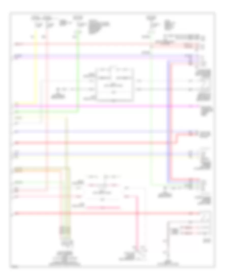
Anti-lock Brakes Wiring Diagram (2 of 2) for Infiniti FX45 2004
List of elements for Anti-lock Brakes Wiring Diagram (2 of 2) for Infiniti FX45 2004:
- Bat
- Brake fluid level switch (left rear of engine compt)
- Can h
- Can l
- Can-h
- Can-l
- Computer data lines system
- Data link connector (lower left side of dash)
- E49 (left side of engine compt)
- E50 (left side of engine compt)
- Early production
- Fuse & fusible link block
- Fuse 12 10a
- Fuse 82 10a
- Fuse block (j/b) (behind left kick panel)
- Fuse i 50a
- Fuse l 30a
- Gnd
- Hot at all times
- Hot in on or start
- Ign
- Interior lights system
- Ipdm e/r (intelligent power distribution module engine room) (right rear of engine compt)
- J/c 2 (left side of dash)
- Late production
- M45 (behind instrument cluster)
- M55
- M56
- Pnk
- Pressure sensor (left rear of engine compt)
- Pwr
- Red
- Sig out
- Steering angle sensor (left side side of dash)
- Stop lamp switch (on brake pedal bracket)
- Unified meter & a/c amplifier (behind center console)
- Vdc off switch
- Yaw rate/side/ decel g sensor (awd) yaw rate/side g sensor (2wd) (under center console, rear of shift selector lever)