ANTI-LOCK BRAKES
Anti-lock Brake Wiring Diagrams for Infiniti G20 t 1999
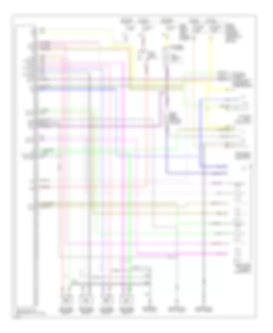
List of elements for Anti-lock Brake Wiring Diagrams for Infiniti G20 t 1999:
- (consult) (at left side of dash, behind fuse box cover)
- Abs actuator (right front corner of engine compt)
- Abs control unit (behind right kick panel)
- Abs motor relay (in relay box)
- Abs solenoid valve relay (in relay box)
- Abs warning lamp
- Bls
- Data link connector
- Diag l
- Diode (abs) (behind left side of dash)
- Ecu gnd
- Fl in
- Fl out
- Fl ss
- Fl ss gnd
- Fr in
- Fr out
- Fr ss
- Fr ss gnd
- Fuse & fusible link box (left front of engine compartment, next to battery)
- Fuse 11 10a
- Fuse 14 15a
- Fuse 3 7.5a
- Fuse block (behind dash, left of steering column)
- Fusible link f 40a
- Fusible link h 40a
- G100 (front of left front fender)
- G101 (front of right front fender)
- G203 (behind right kick panel)
- Gnd1
- Gnd2
- Hot at all times
- Hot in on or start
- Instrument cluster
- Left front wheel speed sensor
- Left rear wheel speed sensor
- Nca
- Pnk
- Red
- Right front wheel speed sensor
- Right rear wheel speed sensor
- Rl in
- Rl out
- Rl ss
- Rl ss gnd
- Rr in
- Rr out
- Rr ss
- Rr ss gnd
- Rxd
- Sila
- Stop lamp switch
- Txd
 English